Internal Bone Fixation Device

a bone fixation device and bone technology, applied in the field of medical devices, can solve the problems of reducing the size affecting the function of the bone column,

Inactive Publication Date: 2020-09-24
ALM ORTHO INC
View PDF0 Cites 12 Cited by
  • Summary
  • Abstract
  • Description
  • Claims
  • Application Information

AI Technical Summary

Benefits of technology

[0008]The non-continuous vertically oriented struts are offset from one another in that one pair of layers are connected by struts connecting the inner rim while a next pair of layers are connected by struts connecting the outer rims, i.e., if the first and second layers are connected at the inner rims the second and third layers are connec

Problems solved by technology

However, these large rims have several drawbacks.
For example, large rims often impede bone growth and reduce the size of the bone column fusing the superior and inferior vertebral bodies.
This often increases the pressure on smaller areas of the vertebral endplates and may potentially lead to stress risers in the vertebral endplates.
Further, while bone graft material is often used

Method used


Image

  • Internal Bone Fixation Device
  • Internal Bone Fixation Device
  • Internal Bone Fixation Device

Examples


first embodiment

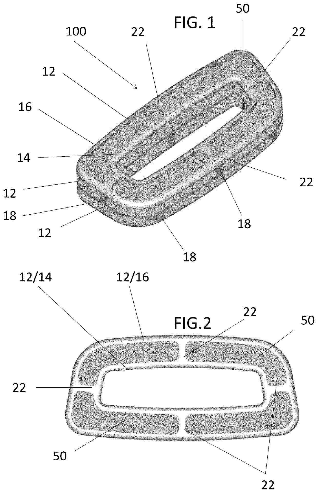
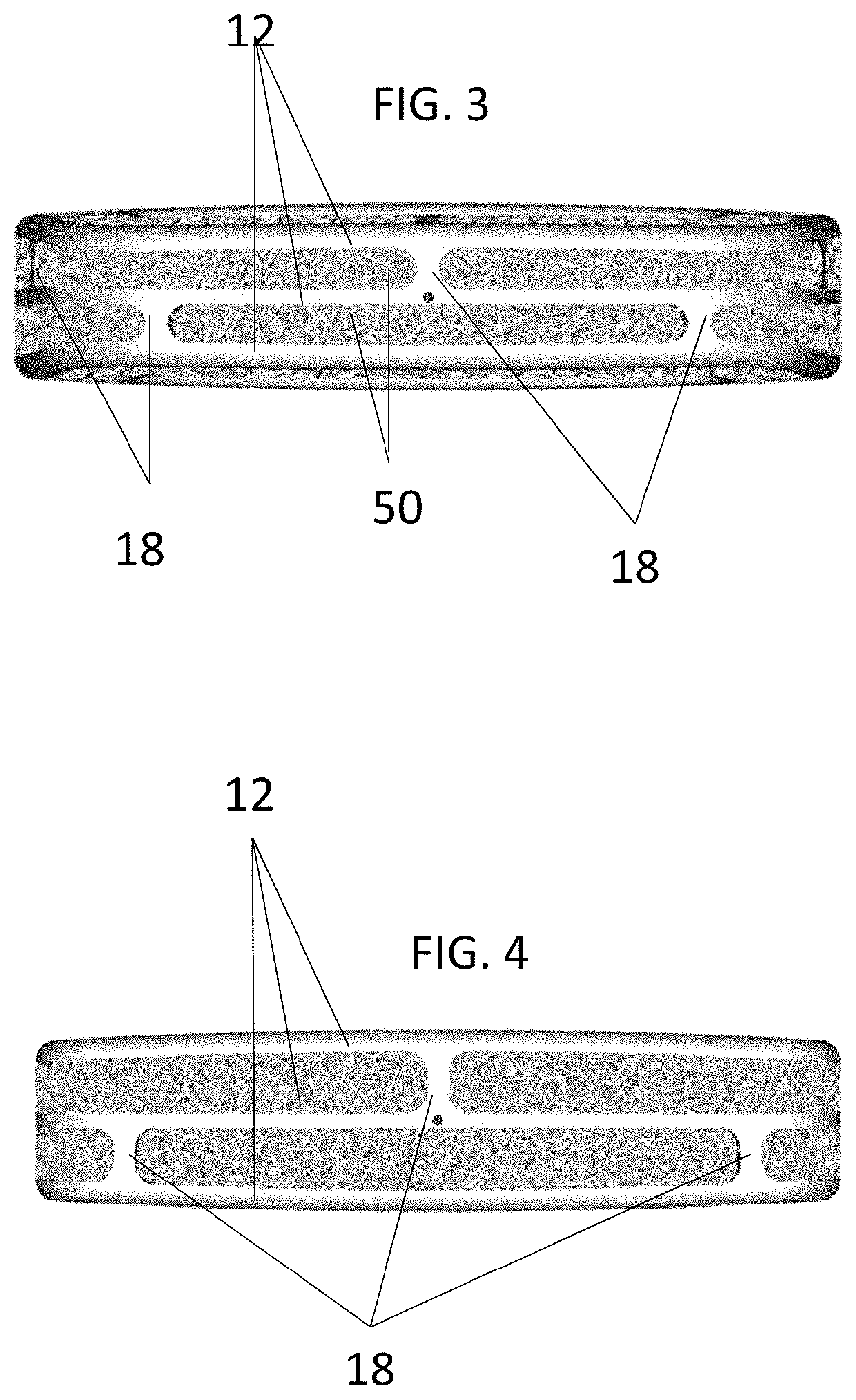
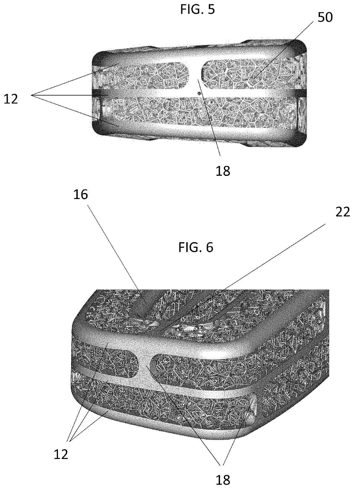
[0046]The outer rim 16 and inner rim 14 in this first embodiment generally have a shape that is approximately in the form of an oval or a rectangle or trapezoid with slightly rounded edges, which is generally intended to be the shape of device needed for lumbar interbody fusion. One side of each rim 14, 16, is slightly narrower than the other. The layers are separated by approximately the same distance from one another, with the layers 12 on side of the device 100 tapered inward slightly. The angle and curvature of the device 100 is intended to match the Lordotic Angle of the area of the spine where the implant is intended to be inserted. The inner rim 14 bounds and defines an open channel through the center of the device. Again, as previously noted, the overall size and / or shape of the device 100 may vary to correspond to the size and / or shape of the cross section of the bones at the fusion or osteotomy site, thereby providing an optimal environment for bone ingrowth to occur.

[0047...

second embodiment

[0054]FIGS. 28 and 29 illustrate the use of this second embodiment as a mid-shaft insert for a long bone, such as the femur F. A longer insert is needed in this instance, and so a total of 13 layers 12 are provided. The off-setting strut arraignment is maintained throughout all 13 layers 12.


PUM


Abstract

An internal bone fixation device that includes a support frame that is strong but able to absorb compressive forces and that surrounds a porous architecture that helps facilitate bone fusion.

Description

BACKGROUND INFORMATIONField of the Invention[0001]The present invention relates generally to medical devices and, more specifically, to implants that aid bone fusion in the body.Discussion of Prior Art[0002]Internal bone fixation devices, or implants, are used in humans and animals to support and / or secure the subject's bones. For example, implants are used in the spine to support and / or replace damaged tissue between the vertebrae in the spine. Once implanted between two vertebrae, the implant provides support between the two vertebrae and bone growth takes place around and through the implant to at least partially fuse the two vertebrae for long-term support.[0003]Implants often include relatively large rims comprised of solid material that may cover, for example, 50% of the area that interacts with the endplate. The rim may provide a contact area between the implant and the vertebral end plates. However, these large rims have several drawbacks. For example, large rims often imped...

Claims


Application Information

Patent Timeline
IPC IPC(8): A61F2/44
CPCA61F2002/30971A61F2/447A61F2002/30112A61F2/28A61F2002/2825A61F2002/285A61F2/4455A61F2/4465A61F2002/4495A61F2002/30014A61F2002/30136A61F2002/3092A61F2002/30782
Inventor MCLAUGHLIN, BRIAN R.
Owner ALM ORTHO INC
Why Eureka
Try Eureka