Power transmission device for four wheel drive vehicle

a technology of transmission device and four-wheel drive vehicle, which is applied in the directions of jet propulsion mounting, transportation and packaging, gearing, etc., can solve the problem that the propeller shaft cannot be disposed in the floor tunnel

Active Publication Date: 2020-09-24
NISSAN MOTOR CO LTD
View PDF0 Cites 1 Cited by
  • Summary
  • Abstract
  • Description
  • Claims
  • Application Information

AI Technical Summary

Benefits of technology

[0008]Thus, the overlapping of the gear case and the rotatable member of the transfer output shaft in the vehicle width direction make it possible to position the transfer output shaft at essentially the center position in the vehicle width direction, and to avoid the inability of locating the propeller

Problems solved by technology

Therefore, if the transfer case is arranged in the same manner as in the conventional device, the location of the transfer output shaft shif

Method used


Image

  • Power transmission device for four wheel drive vehicle
  • Power transmission device for four wheel drive vehicle
  • Power transmission device for four wheel drive vehicle

Examples


first embodiment

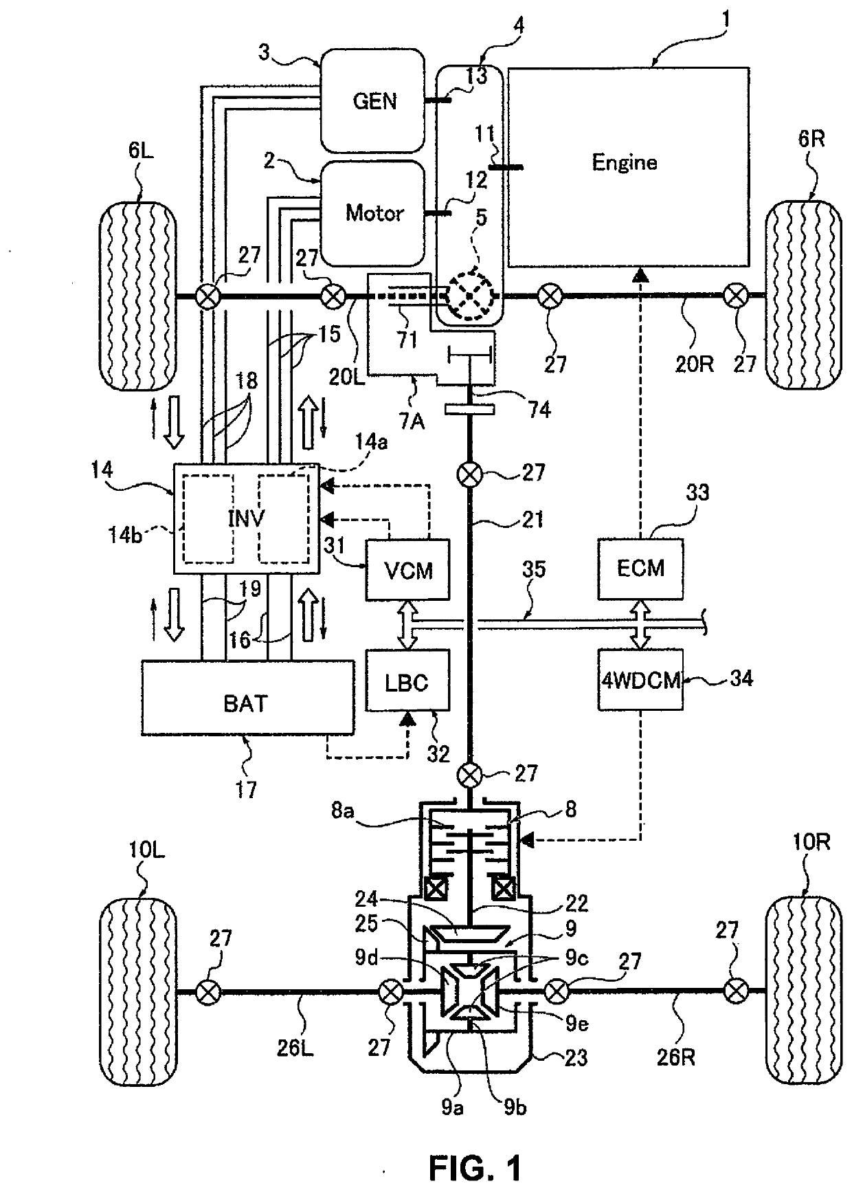
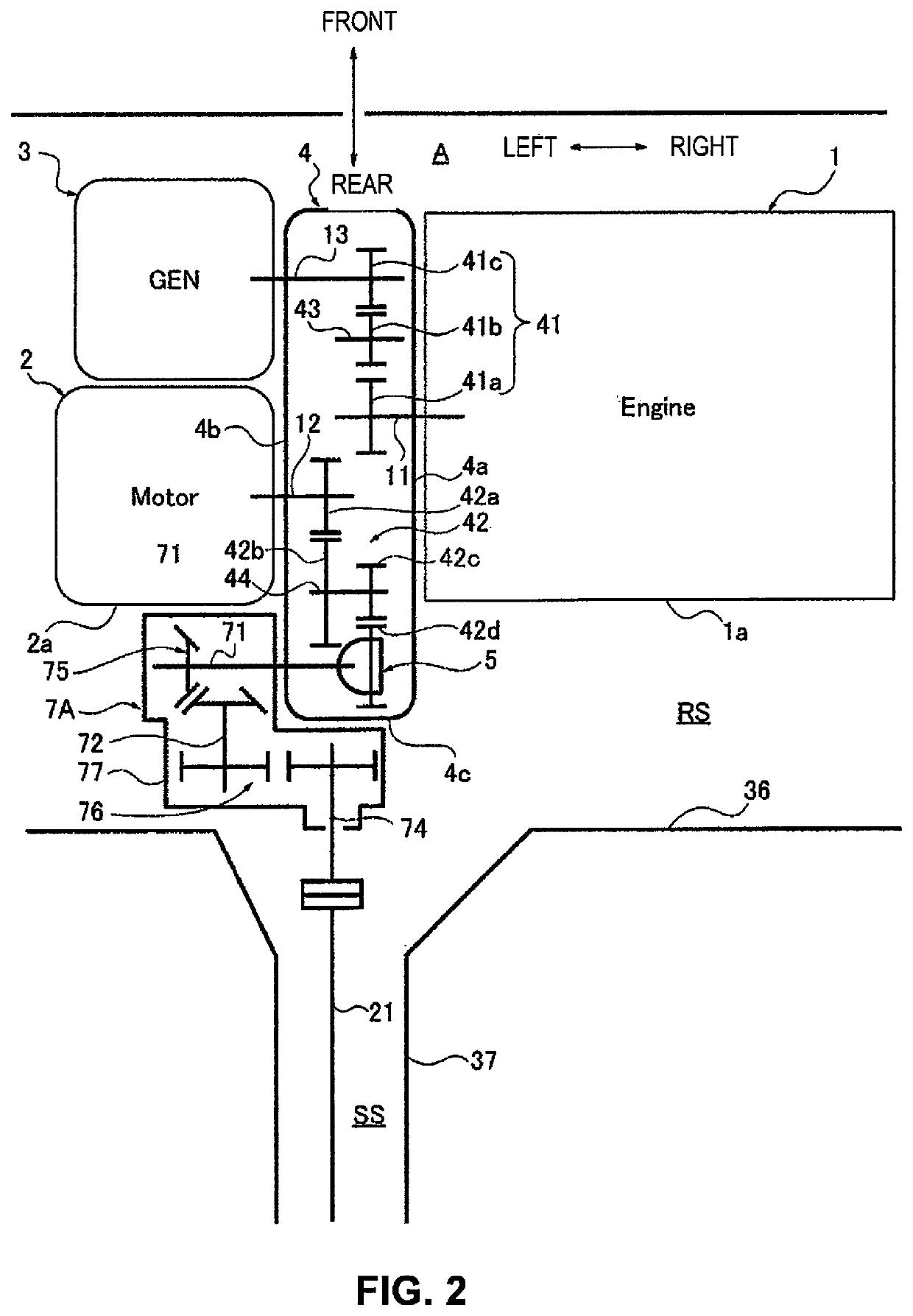
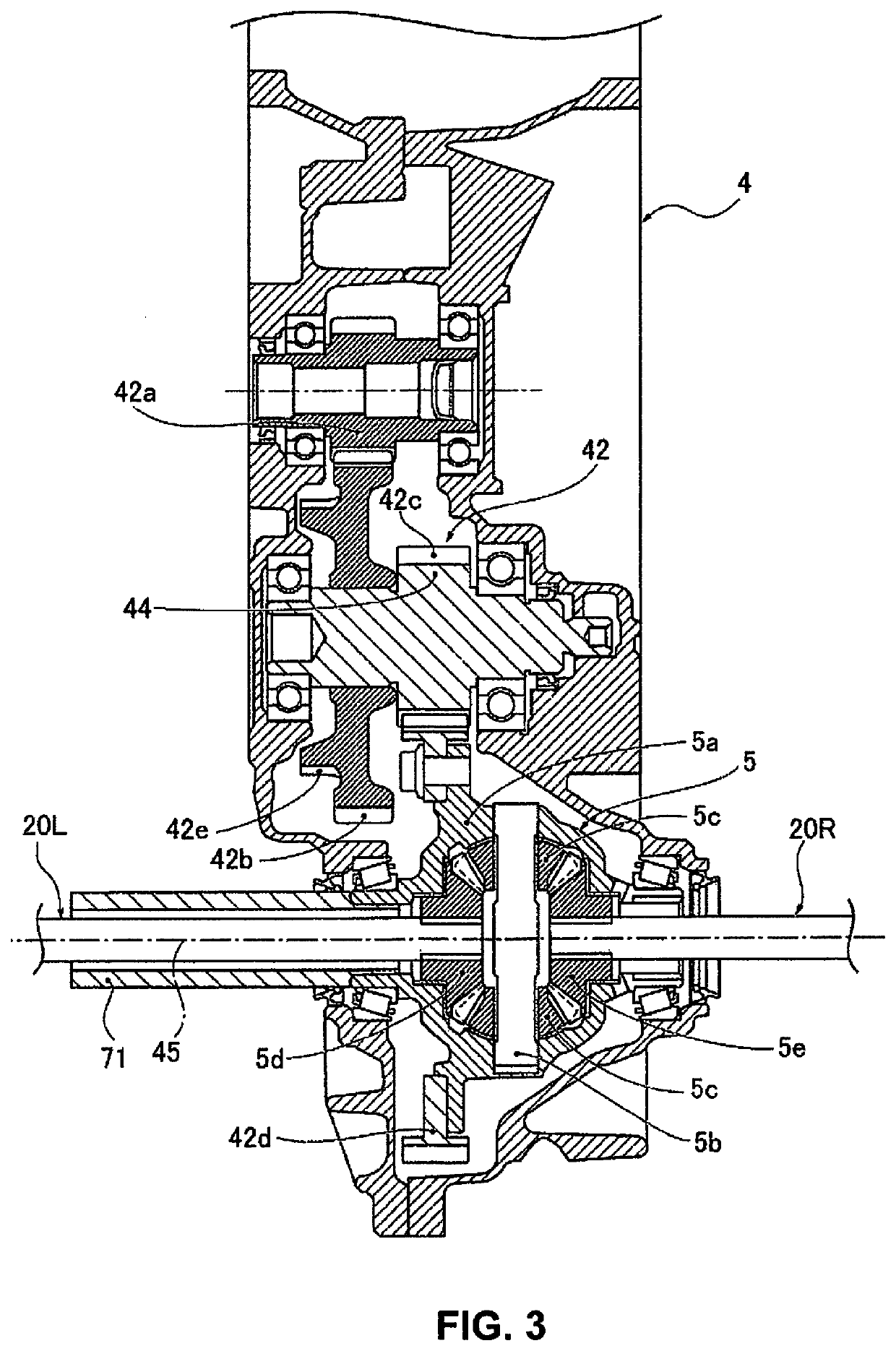
[0021]The configuration is described first. The power transmission device according to the first embodiment is applied to an FF-based four-wheel drive electrically driven vehicle (one example of a four-wheel drive vehicle) that has an engine as a power source for power generation and a motor as a power source for travel, and that uses the electrical power generated by the engine to drive the motor. The “overall system configuration,” the “layout configuration of the front-side power transmission system,” the “detailed configuration of the gear case,” and the “detailed configuration of the transfer case” will be separately described below with respect to the configuration of the first embodiment.

[0022]Overall System Configuration

[0023]FIG. 1 shows an FF-based four-wheel drive electrically driven vehicle to which the power transmission device according to the first embodiment is applied. The overall system configuration of the four-wheel drive electrically driven vehicle will be descr...

second embodiment

[0091]The second embodiment is an example in which the power transmission element of the transfer intermediate shaft and the transfer output shaft is set as a transfer belt instead of the transfer gear of the first embodiment.

[0092]The configuration is described first. The “overall system configuration,” the “layout configuration of the front-side power transmission system,” and the “detailed configuration of the gear case” are the same as in the first embodiment, so that the illustrations and descriptions thereof are omitted. The “detailed configuration of the transfer” of the second embodiment will be described below.

[0093]Detailed Configuration of the Transfer Case

[0094]FIG. 9 shows a detailed configuration of a transfer case 7B supported by the gear case 4 in the power transmission device according to the second embodiment. The detailed configuration of the transfer case 7B will be described below with reference to FIG. 9.

[0095]As shown in FIG. 9, in the transfer case 7B, the tr...

third embodiment

[0108]The third embodiment is an example in which a transfer parallel shaft is used instead of the transfer intermediate shaft of the first and second embodiments, and the power transmission element is a transfer gear pair.

[0109]The configuration is described first. The “overall system configuration,” the “layout configuration of the front-side power transmission system,” and the “detailed configuration of the gear case” are the same as in the first embodiment, so that the illustrations and descriptions thereof are omitted. The “detailed configuration of the transfer” of the third embodiment will be described below.

[0110]Detailed Configuration of the Transfer Case

[0111]FIG. 10 shows a detailed configuration of a transfer case 7C supported by the gear case 4 in the power transmission device according to the third embodiment. The detailed configuration of the transfer case 7C will be described below with reference to FIG. 10.

[0112]As shown in FIG. 10, the transfer case 7C includes the...


PUM


Abstract

In a power transmission device of a four-wheel drive electrically driven vehicle, the power source includes a transverse engine supported on one side surface of a gear case, and a motor supported on the other side surface. A transfer case is supported on the same side surface of the gear case as the motor. The transfer case has a transfer input shaft arranged in the vehicle width direction, a transfer output shaft arranged in the longitudinal direction of the vehicle, a bevel gear pair and a transfer gear pair. The bevel gear pair and the transfer gear pair transmit power by changing a rotational axis direction to an essentially orthogonal direction between the transfer input shaft and the transfer output shaft. An output shaft gear provided on the transfer output shaft of the transfer case is disposed in a position overlapping the gear case in a vehicle width direction.

Description

CROSS-REFERENCE TO RELATED APPLICATIONS[0001]This application is a U.S. national stage application of International Application No. PCT / JP2017 / 038273, filed on Oct. 24, 2017.BACKGROUNDTechnical Field[0002]The present disclosure relates to a power transmission device of a four-wheel drive vehicle comprising a transfer that is supported by a gear case and that distributes power from a power source to main drive wheels and auxiliary drive wheels.Background Information[0003]A power transmission structure of a four-wheel drive vehicle equipped with a transfer case (the power distribution mechanism 1) that is mechanically connected to one power source (the engine 13) via a transmission (the transmission 7) is known from the prior art (for example, refer to Japanese Laid-Open Patent Application No. 2008-110748).SUMMARY[0004]In the conventional device described above, the transfer case (the power distribution mechanism 1) is located on the same one of the two side surfaces of the transmissi...

Claims


Application Information

Patent Timeline
IPC IPC(8): B60K17/348F16H1/20F16H7/02B60K6/24B60K6/26B60K6/36B60K17/24
CPCF16H7/023B60K6/24F16H1/203B60K6/26B60K6/36B60K17/24B60K17/348B60Y2200/92B60K17/344B60K5/04B60K17/35B60K23/08B60K23/0808B60K2023/0833
Inventor KUWABARA, TAKAHIRO
Owner NISSAN MOTOR CO LTD
Why Eureka
Try Eureka