Methods and systems for optically connecting an optical fiber sensor to an optical shape sensing console

a technology of optical fiber sensor and optical shape, applied in the field of optical shape sensing, can solve the problems of exposing patients and medical teams to harmful ionizing radiation, unable to provide critical information about the three-dimensional shape of the medical instrument projection, and using a keyed connector, etc., to achieve the effect of reducing the risk of ionizing radiation exposure and reducing the risk of ionizing radiation

Active Publication Date: 2020-09-24
KONINKLJIJKE PHILIPS NV
View PDF0 Cites 2 Cited by
  • Summary
  • Abstract
  • Description
  • Claims
  • Application Information

AI Technical Summary

Benefits of technology

[0012]It is an object of the present invention to provide a method of and a system for optically connecting an optical fiber sensor to an optical shape sensing console which do not r

Problems solved by technology

However, this imaging technique exposes the patient and the medical team to harmful ionizing radiation.
This projection lacks critical information about the three-dimensional shape of the medical instrument such as its direction and orientation with respect to the anatomy of the patient.
Using a keyed connector, however, has some

Method used


Image

  • Methods and systems for optically connecting an optical fiber sensor to an optical shape sensing console
  • Methods and systems for optically connecting an optical fiber sensor to an optical shape sensing console
  • Methods and systems for optically connecting an optical fiber sensor to an optical shape sensing console

Examples


Embodiment Construction

[0073]In the following, embodiments of a method of and a system for optically connecting an optical fiber sensor to an optical shape sensing console with a correct mutual assignment of the fiber cores and calibration data used in optical shape sensing. The method and system according to the invention is advantageous in shape reconstruction of an optical fiber sensor in three dimensions. Shape reconstruction using an optical fiber sensor may be performed by an optical shape sensing system, an embodiment of which will be first described with reference to FIG. 1.

[0074]As far as not indicated otherwise, an optical fiber sensor can be an optical fiber itself or a device having an optical fiber integrated into the device. Such a device may be, for example a guidewire, a catheter, an endoscope or the like.

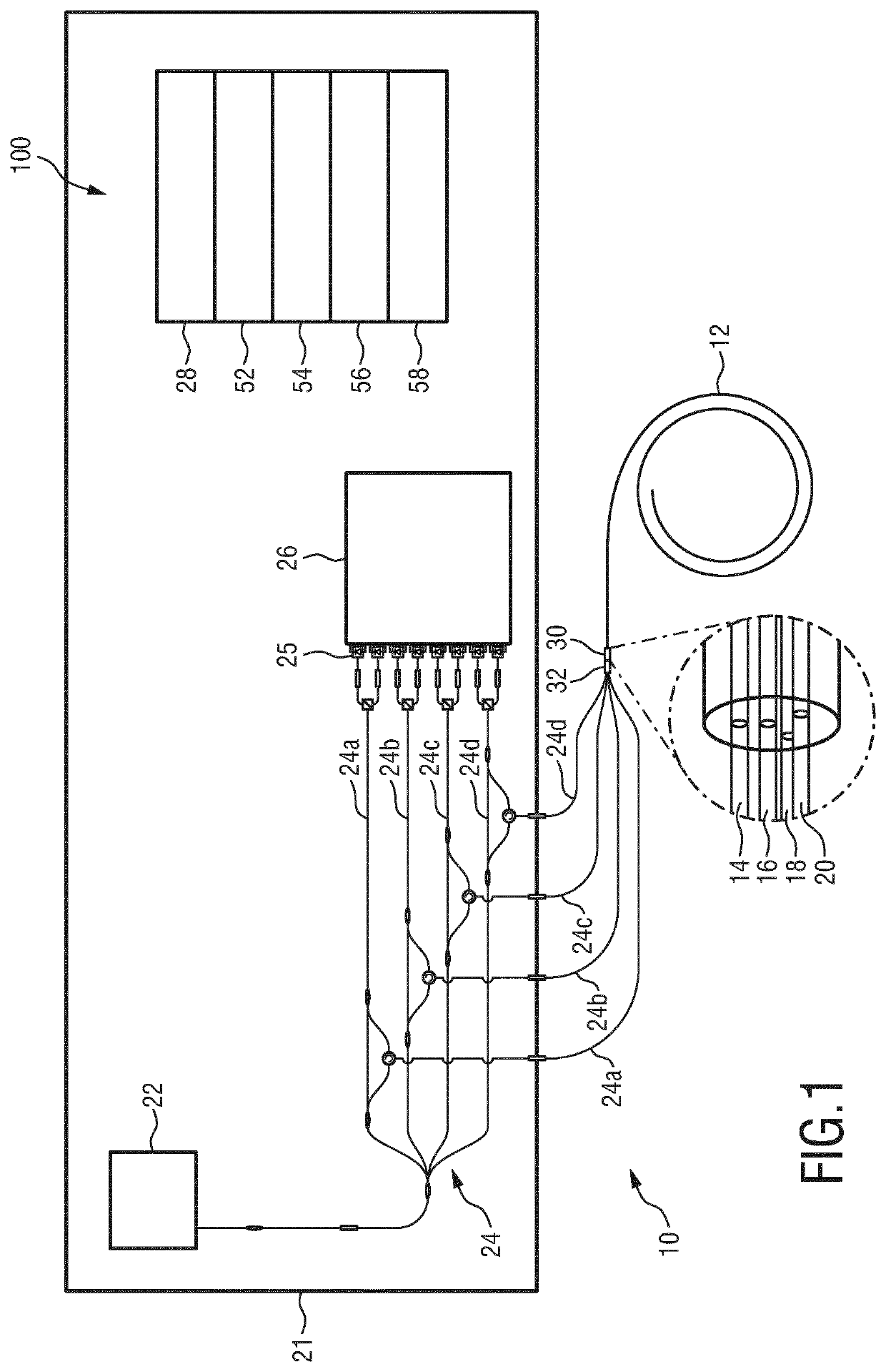
[0075]FIG. 1 shows parts of an optical shape sensing system 12 configured as a multi-channel optical frequency domain reflectometry (OFDR)-based distributed-strain sensing system for sens...


PUM


Abstract

The present invention relates to a method of and a system for optically connecting an optical fiber sensor (12) to an optical shape sensing console (21). The optical shape sensing console (21) has a number of single optical channels (C1, C2, C3). The optical fiber sensor (12) has a number of single fiber cores (A1, A2, A3) angularly spaced with respect to one another around a longitudinal center axis of the fiber sensor (12) and a fiber sensor connection end (30) for connection to an optical coupler (32; 38) connected to the shape sensing console (21). The optical coupler (32; 38) has the optical channels (C1, C2, C3) arranged for optical connection with the fiber cores (A1, A2, A3). A number of single calibration data sets indicative of individual optical properties of the single fiber cores (A1, A2, A3) is assigned to the single optical channels (C1, C2, C3). The fiber sensor connection end (30) is connected to the optical coupler (32; 38) such that a first fiber core (A2) of the fiber cores (A1, A2, A3) is in optical communication with a first optical channel (C1) of the optical channels (C1, C2, C3). An optical response of the first fiber core (A2) is measured by optically interrogating the first fiber core (A2) while a first calibration data set of the calibration data sets is assigned to the first optical channel (C1). The first fiber core (A2) is identified among the fiber cores (A1, A2, A3) of the fiber sensor (12) on the basis of the measured optical response of the first fiber core (A2) and the calibration data sets of the fiber sensor (12). If the first fiber core (A2) is identified as not matching with the first calibration data set used hi measuring the optical response, then a second calibration data set of the calibration data sets, which matches with the identified first fiber core (A2), is reassigned to the first optical channel (C1), or the fiber sensor connection end (30) and/or the optical coupler (32; 38) are repositioned such that a second fiber core (A1) matching with the first calibration data set is in optical communication with the first optical channel (C1).

Description

FIELD OF THE INVENTION[0001]The present invention generally relates to the field of optical shape sensing. In particular, the present invention relates to a method of and a system for optically connecting an optical fiber sensor to an optical shape sensing console, the optical shape sensing console having a number of single optical channels, the optical fiber sensor having a number of single fiber cores angularly spaced with respect to one another around a longitudinal center axis of the fiber sensor and a fiber sensor connection end for connection to an optical coupler connected to the shape sensing console.BACKGROUND OF THE INVENTION[0002]A method and system mentioned above can be used in optical shape sensing of elongated interventional devices, in particular in medical or surgical applications. While the present description refers to the use of optical shape sensing in the medical or surgical field, it is to be understood that the invention is not limited thereto.[0003]In the me...

Claims


Application Information

Patent Timeline
IPC IPC(8): G01B11/16A61B5/06G01D5/353G02B6/02G02B6/42
CPCG02B6/4225G01D5/3538G02B6/02042G01B11/161A61B5/065G02B6/4227G02B6/4222A61B2034/2061G02B6/3831G02B6/3871G01B11/18
Inventor VAN PUTTEN, ELBERT GERJAN
Owner KONINKLJIJKE PHILIPS NV
Why Eureka
Try Eureka