

Robot System And Imaging Method
a robot system and robot technology, applied in the field of robot systems and imaging methods, can solve the problem that the component present at the blind spot of the camera cannot be imaged
- Summary
- Abstract
- Description
- Claims
- Application Information
AI Technical Summary
Benefits of technology
Problems solved by technology
Method used
Image



Examples
first embodiment
Overview of a First Robot System
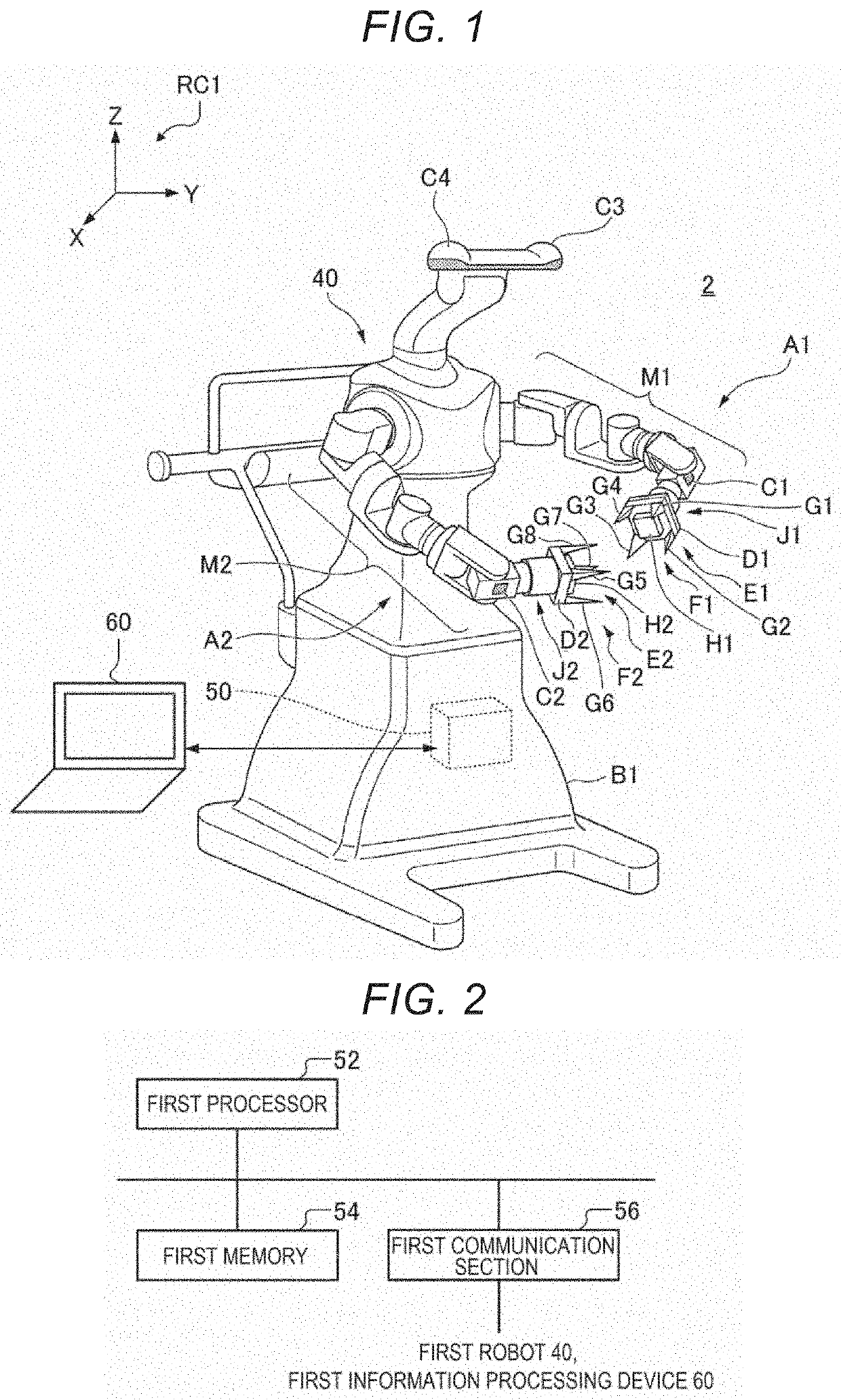
[0039]FIG. 1 is a diagram showing an example of the configuration of a first robot system 2 according to a first embodiment.
[0040]The first robot system 2 functioning as a robot system according to this embodiment includes a first robot 40 functioning as a robot and a first information processing device 60. The first robot 40 incorporates a first robot control device 50 functioning as a control section. The first robot system 2 may not include the first information processing device 60.
[0041]Instead of incorporating the first robot control device 50, the first robot 40 may be controlled by the first robot control device 50 set on the outside of the first robot 40. In this case, the first robot system 2 includes the first robot 40 and the first robot control device 50.
[0042]The first robot system 2 may include, in addition to both of the first robot 40 and the first information processing device 60, another device such as an imaging section separate fr...
second embodiment
[0154]FIG. 12 is a flowchart showing an imaging method of the first robot system 2 according to a second embodiment. FIG. 13 is a schematic side sectional view showing a positional relation between the third imaging section C3 and the container 10. Specifically, FIG. 13 shows a positional relation between the third imaging section C3 and the container 10 before being drawn out from the shelf 14. FIG. 14 is a schematic side sectional view showing a state in which the grip 12 of the container 10 is held by the first end effector E1. FIG. 15 is a schematic side sectional view showing a positional relation between the third imaging section C3 and the container 10. Specifically, FIG. 15 shows a positional relation between the third imaging section C3 and the container 10 drawn out from the shelf 14. FIG. 16 is a schematic side sectional view showing a positional relation between the third imaging section C3 and the container 10. Specifically, FIG. 16 shows a positional relation between t...
third embodiment
[0172]FIG. 18 is a schematic side sectional view showing a positional relation between the second imaging section C2 and the container 10 according to a third embodiment. Specifically, FIG. 18 shows a positional relation between the second imaging section C2 and the container 10, the front of which is lowered in the downward direction, which is the vertical direction.
[0173]An imaging method of the first robot 40 is explained below with reference to FIG. 18.
[0174]The first robot 40 according to this embodiment is different from the first robot 40 according to the first embodiment in that the first robot 40 according to this embodiment images the container 10 with the second imaging section C2. The same components as the components in the first embodiment are denoted by the same reference numerals and signs. Explanation of the components is omitted or simplified.
[0175]The first robot 40 according to this embodiment images the container 10 with the second imaging section C2 included in...
PUM
 Abstract
Description
Claims
Application Information