Blade set and manufacturing method

a manufacturing method and technology of a blade set, applied in the direction of metal working apparatus, etc., can solve the problems of relatively high manufacturing cost, relatively complex and cost-increasing auxiliary processes, and the blade is not actively actuated, so as to facilitate styling operations and hair cutting operations, the effect of flexible deploymen

Pending Publication Date: 2020-10-08
KONINKLJIJKE PHILIPS NV
View PDF26 Cites 6 Cited by
  • Summary
  • Abstract
  • Description
  • Claims
  • Application Information

AI Technical Summary

Benefits of technology

[0070]In some embodiments, the blade set is provided with two opposite leading edges, i.e. two opposite series of stationary blade teeth and movable blade teeth. In this way, both a pulling and a pushing movement of the

Problems solved by technology

However, the stationary blade is not arranged to be actively actuated to cause a cutting action.
However, at least some of the above-indicated approaches still involve relatively high manufac

Method used


Image

  • Blade set and manufacturing method
  • Blade set and manufacturing method
  • Blade set and manufacturing method

Examples


Embodiment Construction

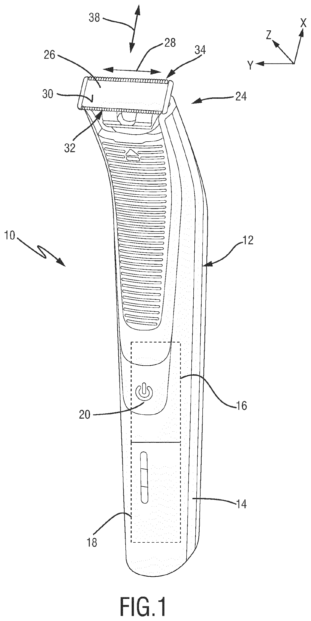
[0085]FIG. 1 shows a perspective frontal view of a hair cutting appliance 10. The hair cutting appliance 10 is arranged as an appliance that is capable of both trimming and shaving.

[0086]The appliance 10 comprises a housing 12 which is arranged in an elongated fashion. At the housing 12, a handle section 14 is defined. In the housing 12, a drive unit 16 is arranged. Further, a battery 18 may be arranged in the housing 12. In FIG. 1, the drive unit 16 and the battery 18 are represented by dashed blocks. At the housing 12, operator controls 20 such as on / off buttons and the like may be provided.

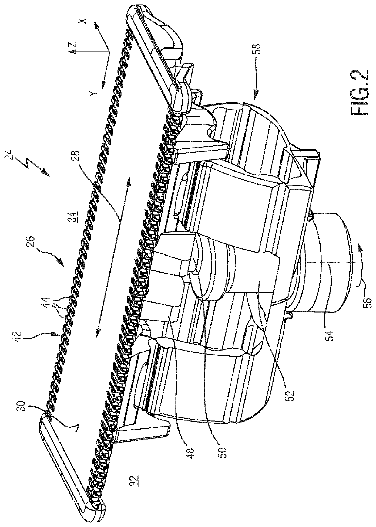
[0087]At a top end thereof, the appliance 10 comprises a processing head 24 that is attached to the housing 12. The processing head 24 comprises a blade set 26. The blade set 26, particularly a movable blade thereof, may be actuated and driven by the drive unit 16 in a reciprocating fashion, refer also to the double arrow 28 in FIG. 1. As a result, respective teeth of the blades of the blade se...


PUM


Abstract

The present disclosure relates to a blade set (26) for a hair cutting appliance (10), said blade set (26) being arranged to be moved through hair in a moving direction (38) to cut hair, said blade set (26) comprising a stationary blade (42) comprising a support insert (70) and a metal component (68), wherein the metal component (68) and the support insert (70) are force-fitted to one another, wherein the metal component (68) is at least sectionally deformed to define at least one toothed leading edge (32, 34) having double-walled stationary blade teeth (44), wherein the metal component (68) forms a first wall (100) that is arranged to serve as a skin-facing wall when in operation, and a second wall (102) that is facing away from the first wall (100), and wherein a guide slot (60) for a movable blade (62) is defined between inwardly facing inner surfaces of the metal component (68) and the support insert (70), and a movable blade comprising a plurality of movable blade teeth (64), wherein the movable blade (62) is movably arranged between the metal component (68) and the support insert (70) in the guide slot (60), and wherein the movable blade (62) is, in the mounted state, preloaded and movably arranged in the guide slot (60) between the metal component (68) and the support insert (70). The disclosure further relates to a corresponding manufacturing method.

Description

FIELD OF THE INVENTION[0001]The present disclosure relates to a blade set of a hair cutting appliance and to a respectively equipped hair cutting appliance. Further, the present disclosure relates to a method of manufacturing a blade set for a hair cutting appliance.BACKGROUND OF THE INVENTION[0002]WO 2013 / 150412 A1 discloses a stationary blade for a blade set of an electrically operated hair cutting appliance, the blade including a first wall and a second wall, each wall defining a first surface, a second surface facing away from the first surface, and a laterally extending leading edge defining a plurality of laterally spaced apart longitudinally extending projections, wherein the first surfaces of the first and second walls face each other, at least at their leading edges, while facing projections along the leading edges of the first and second walls are mutually connected at their tips to define a plurality of generally U-shaped teeth, and the first surfaces of the first and sec...

Claims


Application Information

Patent Timeline
IPC IPC(8): B26B19/38B26B19/06
CPCB26B19/06B26B19/3893B26B19/3846B23P15/403B26B19/042B26B19/04
Inventor PHOON, KIN FATT
Owner KONINKLJIJKE PHILIPS NV
Why Eureka
Try Eureka