
Support structure for brake fluid pressure generation device

Active Publication Date: 2020-10-08
TOYOTA JIDOSHA KK
View PDF0 Cites 1 Cited by
  • Summary
  • Abstract
  • Description
  • Claims
  • Application Information

AI Technical Summary

Benefits of technology

The present invention provides a support structure for brake fluid pressure generation devices in electric vehicles. The support structure helps to reduce vibrations and prevent them from being transmitted to the vehicle cabin. The support structure includes brackets and a rubber elastic body, which helps to disperse the load and avoid concentration of force on one point in the support member. This support structure also ensures that the brake fluid pressure generation devices are relatively small in size, which makes it comfortable for the occupants of the vehicle. Overall, the support structure improves the comfort and safety of the electric vehicle by reducing vibrations and noise.

Problems solved by technology

However, the structure in which the master cylinder that is electrically controlled is supported by the dash panel has such a problem that, when an electric motor is actuated, the dash panel is shaken, so that large vibrations are transmitted into the vehicle cabin.
Such a problem also occurs in a structure in which a brake actuator or the like is supported by the dash panel.

Method used


Image

  • Support structure for brake fluid pressure generation device
  • Support structure for brake fluid pressure generation device
  • Support structure for brake fluid pressure generation device

Examples


Embodiment Construction

[0041]With reference to the drawings, the following describes an embodiment to carry out the present disclosure.

[0042]Overall Configuration of Vehicle

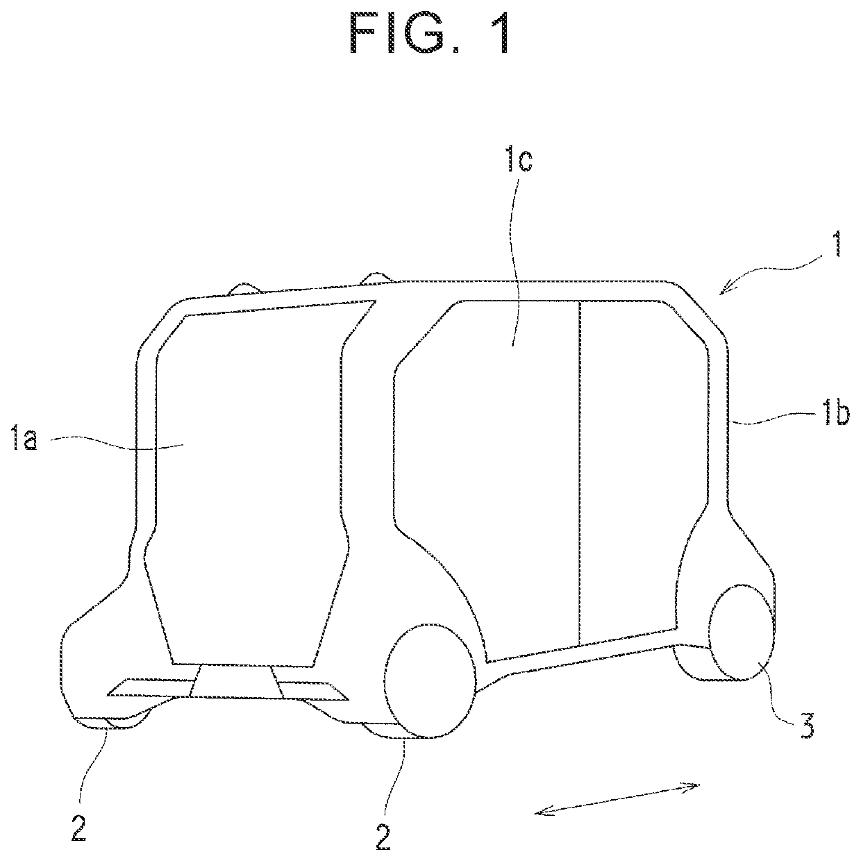
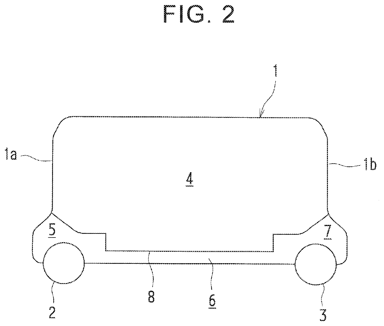
[0043]FIG. 1 is a perspective view schematically illustrating a vehicle 1 according to the present embodiment. As illustrated in FIG. 1, the vehicle 1 has an external appearance that is greatly different from conventional general vehicles in that, for example, its vehicle body is almost symmetrical in an advancing direction (see an arrow in FIG. 1), wheels 2, 3 are arranged extremely close to both ends of the vehicle, respectively, there is no hood or the like covering an engine compartment (a motor room), and an almost entire surface of a vehicle side face 1c is configured as a doorway.

[0044]Note that, since the vehicle 1 can advance to both sides in the advancing direction in generally the same mode, there is no concept of a front side and a rear side in the vehicle 1. However, for convenience, the left side in FIG. 1 is described as...


PUM


Abstract

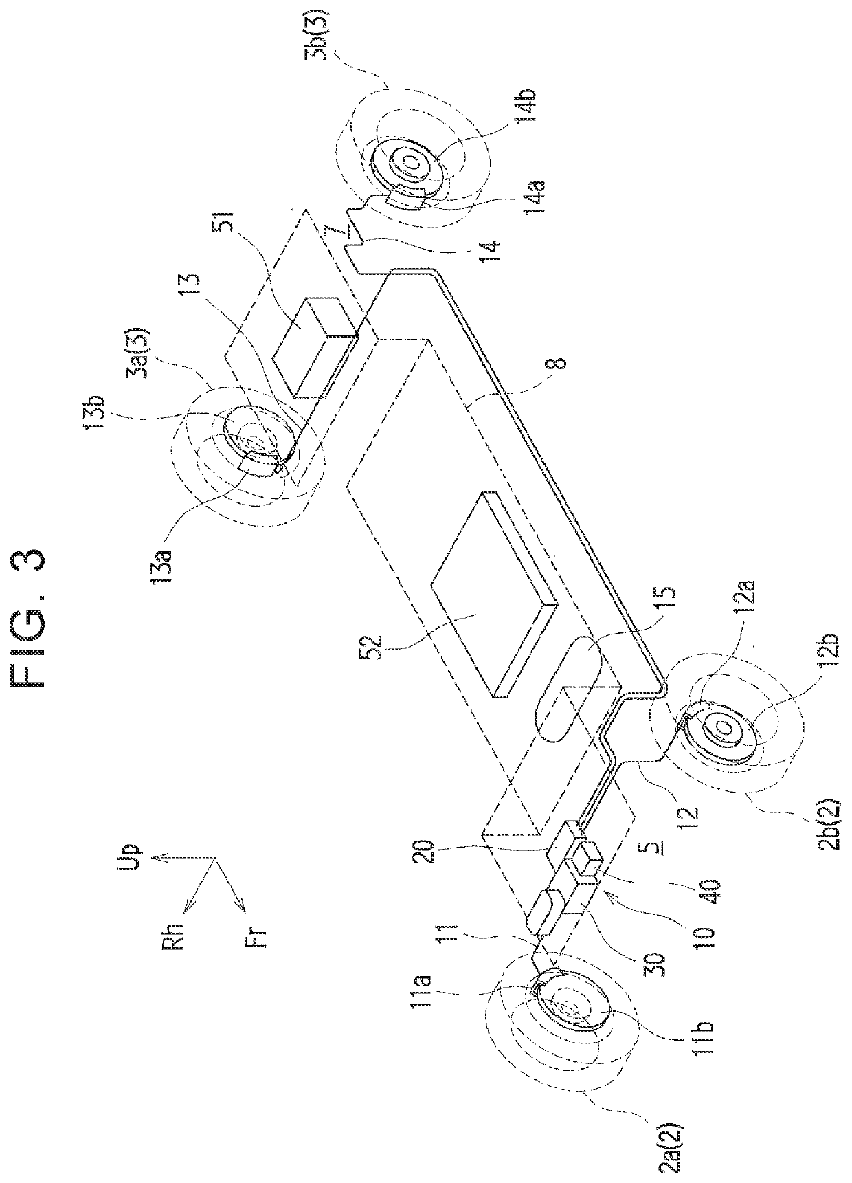
Provided is a support structure for a plurality of electrically actuated brake fluid pressure generation devices provided in a vehicle in which automated driving is enabled, the brake fluid pressure generation devices being configured to generate brake fluid pressure. The support structure includes a support member (a first bracket, a second bracket, and an actuator bracket) via which a brake actuator and a brake unit are supported by frame members forming a storage chamber separated from a vehicle cabin. The support member is supported by the frame members at two points. The brake actuator and the brake unit are mechanically connected to each other via the support member.

Description

INCORPORATION BY REFERENCE[0001]The disclosure of Japanese Patent Application No. 2019-071275 filed on Apr. 3, 2019 including the specification, drawings and abstract is incorporated herein by reference in its entirety.BACKGROUND1. Technical Field[0002]The present disclosure relates to a support structure for a brake fluid pressure generation device, especially to a support structure for a plurality of brake fluid pressure generation devices provided in a vehicle in which automated driving is enabled.2. Description of Related Art[0003]In the related art, there has been known an electric braking device configured to electrically control brake fluid pressure such that a brake for a vehicle is actuated without depending on stepping force applied by a driver.[0004]For example, Japanese Patent No. 4639118 (JP 4639118 B) describes a vehicle brake fluid pressure control device that achieves an excellent operation feeling by creating an operation feeling of a brake pedal by a feeling creati...

Claims


Application Information

Patent Timeline
IPC IPC(8): B60T17/08B60T13/68
CPCB60T8/4031B60T13/686B60T17/088B60T13/12B60T13/142B60T17/06B60T7/06B60T13/745B60T7/22B60T11/16B60T13/662B60T13/683
Inventor FUJIMOTO, TETSUYA
Owner TOYOTA JIDOSHA KK
Learn More