Generalized polar code construction

a polar code and generalization technology, applied in the field of wireless communication, can solve the problem that the decoding performance on the receiver side can be a limiting factor to the achievable data ra

Inactive Publication Date: 2020-10-08
QUALCOMM INC
View PDF0 Cites 11 Cited by
  • Summary
  • Abstract
  • Description
  • Claims
  • Application Information

AI Technical Summary

Problems solved by technology

As data rates increase, decoding performance on the receiver side can be a limiting factor to achievable data rates.

Method used


Image

  • Generalized polar code construction
  • Generalized polar code construction
  • Generalized polar code construction

Examples


example generalized

Polar Code Construction

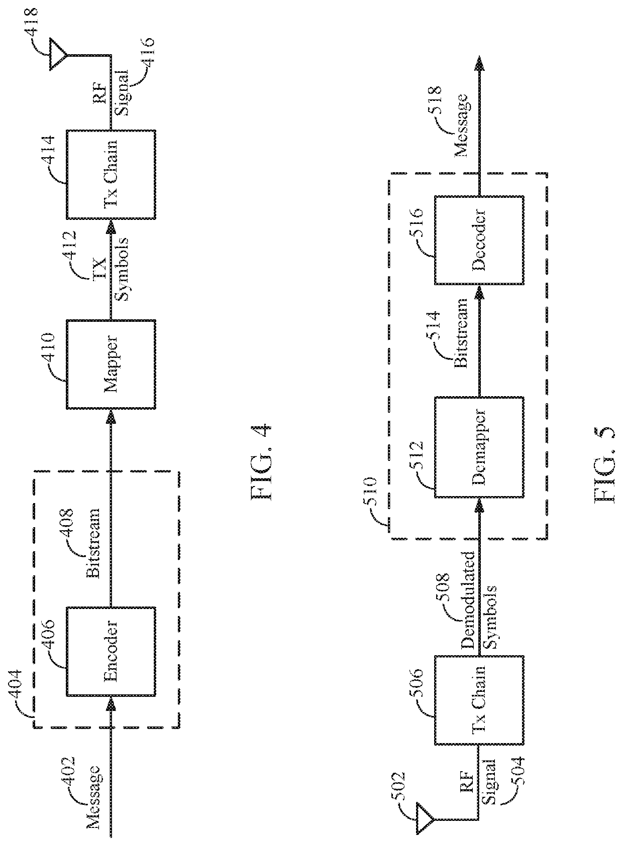
[0094]According to certain aspects, rather than using a polar code in both dimensions (i.e., both ‘k’ and ‘m’ dimensions, as described above), a non-polar code (e.g., Reed-Muller code or extended Hamming codes or the Reed-Muller-Polar hybrid codes) could be used in a first dimension (e.g., the K-dimension) and a polar code in a second dimension. For example, a base station can first encode the information bits (for each row) using a general non-polar code of appropriate rate (e.g., less than the capacity of the corresponding polarized channel) and then each column may be multiplied by the Hadamard matrix of size M to obtain the final code. In other words, a base station may use a first code (e.g., Reed-Muller, extended Hamming codes, etc.) to encode information bits in a first dimension, and may use a second code (e.g., a Polar code) to further encode the information bits in a second dimension, resulting in a codeword that is the product of the first and secon...


PUM


Abstract

Certain aspects of the present disclosure relate to techniques and apparatus for improving decoding latency and performance of Polar codes. An exemplary method generally includes generating a codeword by encoding information bits using a first code of length K to obtain bits for transmission via K channels, wherein the first code comprises a polar code, further encoding the bits in each of the K channels using a second code of length M, and transmitting the codeword.

Description

CLAIM OF PRIORITY UNDER 35 U.S.C. § 119[0001]This application claims priority to U.S. application Ser. No. 15 / 395,749, filed Dec. 30, 2016, which claims benefit of U.S. Provisional Patent Application Ser. No. 62 / 344,031, filed Jun. 1, 2016 and entitled “GENERALIZED POLAR CODES FOR IMPROVED PERFORMANCE AND LATENCY,” which are both herein incorporated by reference in their entirety.TECHNICAL FIELD[0002]The technology discussed below generally relates to wireless communications and, more particularly, to a method and apparatuses for improving decoding latency and performance of Polar codes, for example, by strategic placement of CRC bits. Embodiments enable and provide coding techniques that can be used on varying sizes of data packets and may be used for control / data channels as desired.INTRODUCTION[0003]In a transmitter of all modern wireless communication links, an output sequence of bits from an error correcting code can be mapped onto a sequence of complex modulation symbols. Thes...

Claims


Application Information

Patent Timeline
Patent Type & Authority Applications(United States)
IPC IPC(8): H04L1/00H03M13/13
CPCH03M13/09H04L1/0041H04L1/0045H04L1/0054H03M13/13H04L1/0057H04L1/0061
Inventor KUDEKAR, SHRINIVASRICHARDSON, THOMAS JOSEPH
Owner QUALCOMM INC
Why Eureka
Try Eureka