Torque Wrench for Implant Procedure

a technology for wrenches and implants, applied in wrenches, medical science, surgery, etc., can solve the problems of inconvenient operation, inability to fasten screws, and inconvenient operation, so as to shorten the procedure time, efficient fastening and removal, and ensure the effect of accuracy and stability

Active Publication Date: 2020-10-15
DENFLEX CO LTD
View PDF2 Cites 5 Cited by
  • Summary
  • Abstract
  • Description
  • Claims
  • Application Information

AI Technical Summary

Benefits of technology

[0018]First, it is possible to first tighten the screw and finally firmly fasten the screw or to loosen the screw and completely remove the screw by using only a single torque wrench according to the present invention, even without the use of a separate hand driver. This makes it possible to prevent the problem that an operator may accidentally drop the driver and a patient may swallow the driver during a procedure.
[0019]Second, the present invention is configured to enable a screw to be efficiently fastened and removed with only a single torque wrench, thereby enabling a more precise and stable procedure, as well as to shortening a procedure time.
[0020]Third, it is possible to eliminate cumbersome operation of having to provide a hand driver and a torque wrench at the same time and having to exchange the driver for the wrench during a procedure of fastening or removing a screw.

Problems solved by technology

In particular, when the male screw is tightened with the torque wrench in a state in which the male screw and the female screw are not engaged or are not fully engaged, there is a problem in that the torque wrench may not rotate properly and fail to fasten the screws.
Likewise, when loosening the firmly tightened screw, the screw has to be loosened with the torque wrench to a certain degree, and then finally the hand driver has to be used again for complete removal, which is a cumbersome process.
In particular, in the case of a patient whose mouth is hard to open, it may not easy to accurately position and tighten the hand driver directly on the fastening site in the oral cavity.
In some cases, the operator may accidentally drop the driver in the oral cavity.

Method used


Image

  • Torque Wrench for Implant Procedure
  • Torque Wrench for Implant Procedure
  • Torque Wrench for Implant Procedure

Examples


Embodiment Construction

[0026]Hereinafter, exemplary embodiments of the present invention will be described in more detail with reference to the accompanying drawings.

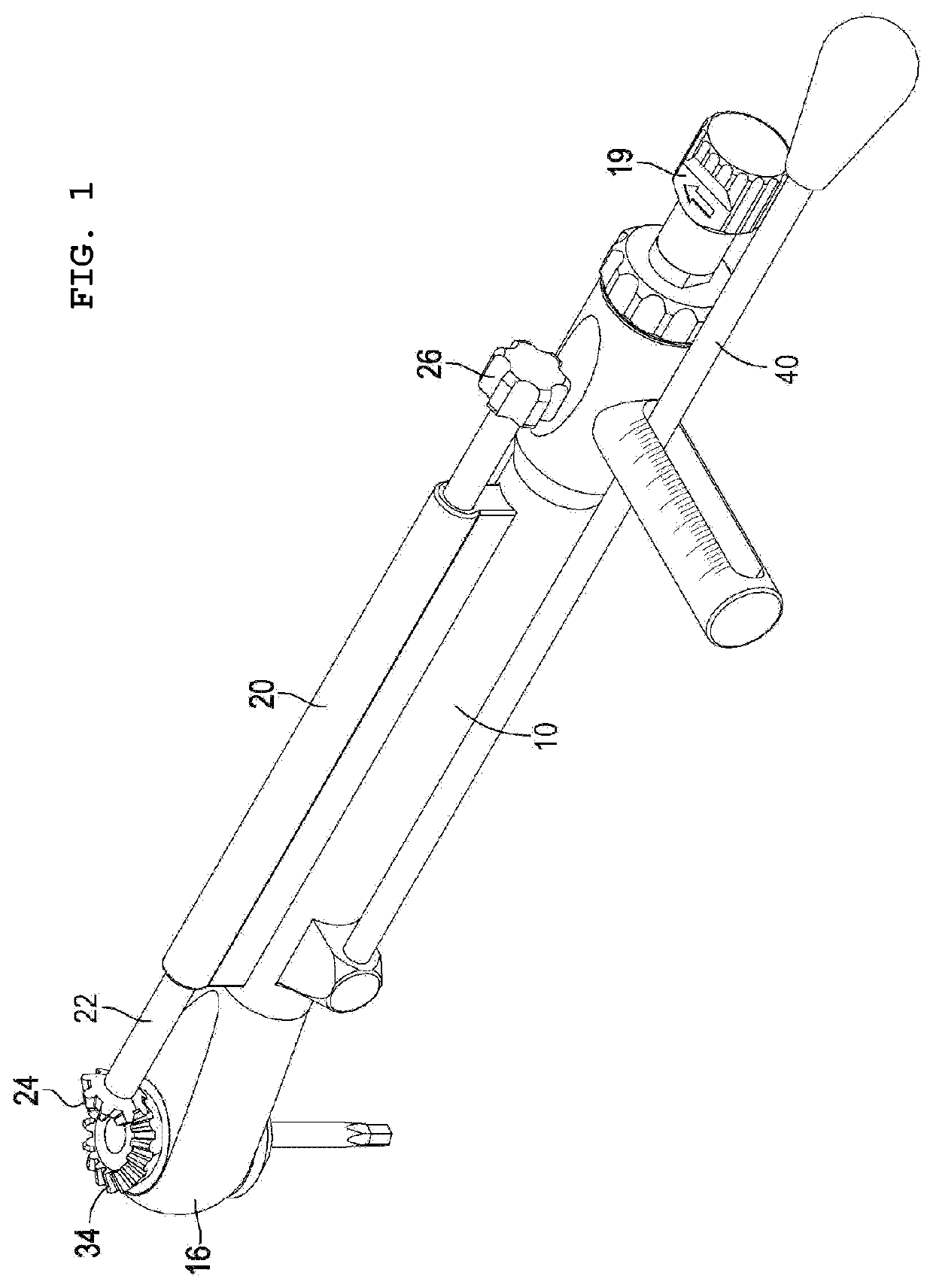
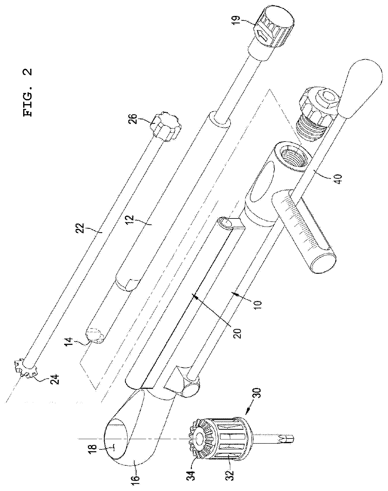
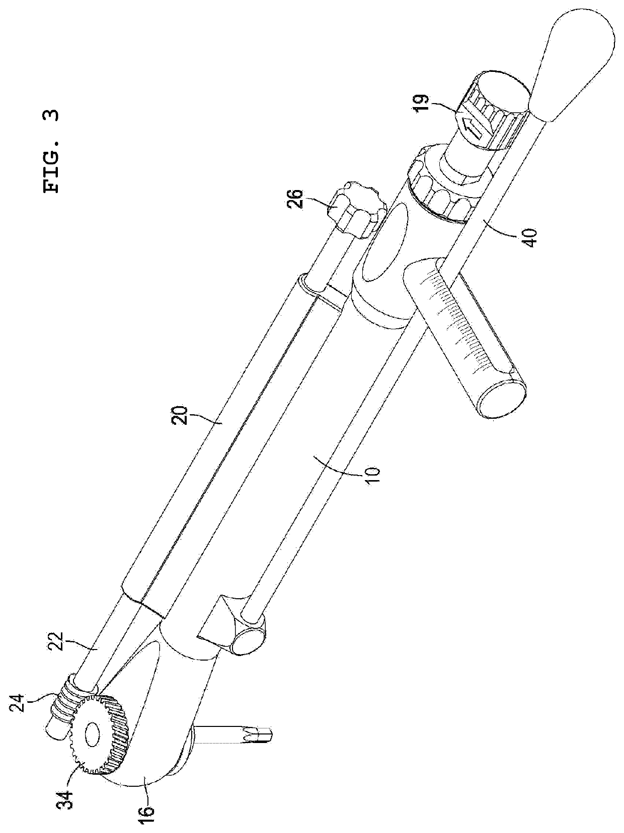
[0027]FIG. 1 is a perspective view illustrating a torque wrench according to an embodiment of the present invention, and FIG. 2 is an exploded perspective view illustrating the torque wrench according to the embodiment of the present invention. Referring to FIGS. 1 and 2, a torque wrench for an implant procedure according to an embodiment of the present invention includes: a first body part 10 having a predetermined length, and including a head portion 16 in which a fastening hole 18 is formed at an end thereof to allow a torque wrench driver bit 30 to be detachably coupled thereto; at least one second body part 20 having a predetermined length, provided at one side of the first body part 10, and including a coupling portion formed in a longitudinal direction thereof; and a second shaft 22 rotatably coupled to the coupling portion of the seco...


PUM


Abstract

A torque wrench for an implant procedure is provided, wherein only a single torque wrench according to the present invention is necessary to first tighten a screw and finally firmly fasten the screw with a desired force or to first loosen the screw and finally completely remove the screw, even without the use of a separate hand driver. A torque wrench for an implant procedure includes: a first body part having a predetermined length, and including a head portion having an end to which a torque wrench driver bit is coupled; at least one second body part having a predetermined length, provided at one side of the first body part, and including a coupling portion formed in a longitudinal direction thereof; and a second shaft rotatably coupled to the coupling portion of the second body part, including a second gear provided at one end thereof and a knob provided at the other end thereof, and configured such that, in response to rotation of the knob, the second shaft transmits torque to the torque wrench driver bit through the first gear engaged with the second gear.

Description

CROSS-REFERENCE TO EARLIER FILED APPLICATIONS[0001]The present application is a continuation of and claims the benefit of PCT / KR2020 / 002672 filed Feb. 25, 2020, which claims the benefit of foreign application KR 10-2019-0152000 filed Nov. 25, 2019 and KR 10-2019-0041977 filed Apr. 10, 2019, the entire disclosures of which are hereby incorporated by reference.FIELD OF THE INVENTION[0002]The present invention relates generally to a torque wrench for an implant procedure. More particularly, the present invention relates to a torque wrench for an implant procedure, wherein only a single torque wrench according to the present invention is necessary to first tighten a screw and finally firmly fasten the screw with a desired force or to first loosen the screw and finally completely remove the screw, even without the use of a separate hand driver.BACKGROUND OF THE INVENTION[0003]An implant denotes a replacement for restoring lost human tissue. In the field of dentistry, the implant in gener...

Claims


Application Information

Patent Timeline
Patent Type & Authority Applications(United States)
IPC IPC(8): A61C8/00A61B17/88A61C1/18B25B23/142
CPCA61B2090/066A61B17/8875A61C8/0089A61C1/186B25B23/1427B25B17/02A61B2090/031A61B17/88
Inventor KIM, HYUNG-WOO
Owner DENFLEX CO LTD
Why Eureka
Try Eureka