Apparatus and method for measuring magnetic properties of a ferromagnetic endless belt

Pending Publication Date: 2020-10-15
DR BROCKHAUS MESSTECHN
View PDF2 Cites 0 Cited by
  • Summary
  • Abstract
  • Description
  • Claims
  • Application Information

AI Technical Summary

Benefits of technology

The invention is a device and technique that can measure the magnetic loss power of an endless belt with high precision across its width. This allows for continuous monitoring of the belt's operating performance.

Problems solved by technology

On the basis of this prior art, an apparatus for continuous measurement, a so-called inline measurement, of an endless belt is desirable, which in particular results in the loss power in the case of an alternating field excitation with the highest possible local resolution over the width of the endless belt.

Method used


Image

  • Apparatus and method for measuring magnetic properties of a ferromagnetic endless belt
  • Apparatus and method for measuring magnetic properties of a ferromagnetic endless belt
  • Apparatus and method for measuring magnetic properties of a ferromagnetic endless belt

Examples


Embodiment Construction

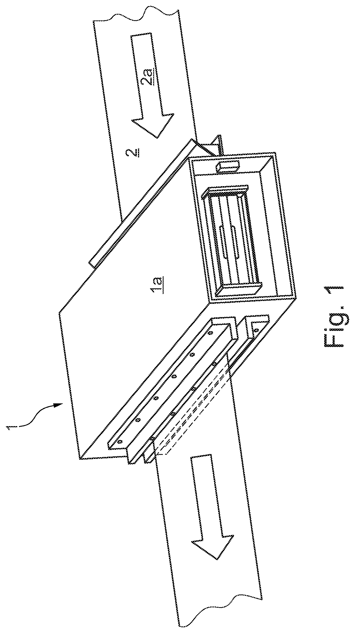
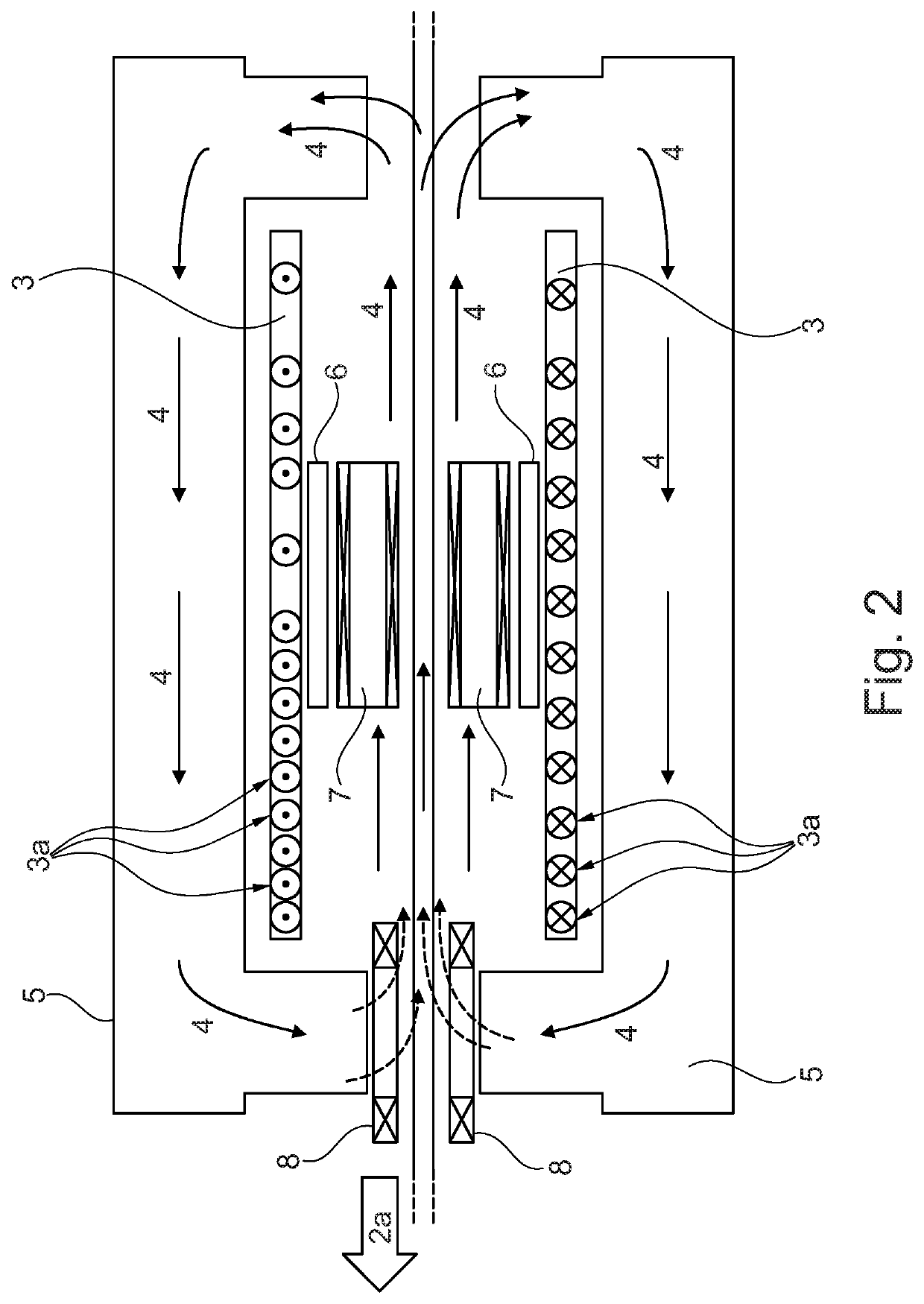
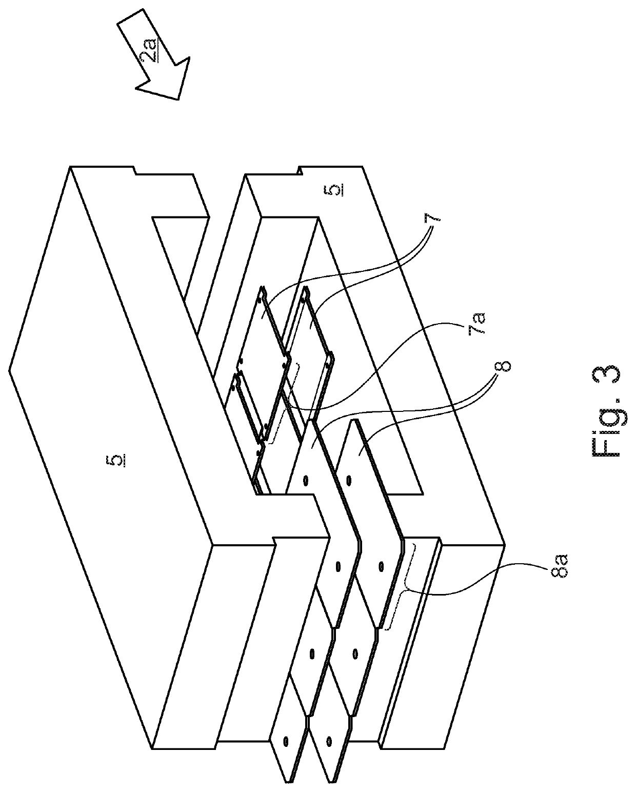
[0017]In the figures described below, the same reference numerals designate the same elements of the schematically illustrated apparatus. The figures are neither to scale nor do they show all the details; they only serve to illustrate various arrangements of the apparatus. The figures show schematic views of the apparatus, substantially showing the arrangement of the excitation coil and the sensors or measuring coils. For the sake of clarity, the elements of the electrics and electronics for triggering the excitation coil and the electronics for evaluating the signals from the sensors or measuring coils are not shown, since the structure and the triggering result from the following for the person skilled in the art.

[0018]In the embodiment of the invention described below, the field coils are arranged above and below the endless belt in order to be able to compensate for fluctuations in the distance between a coil and the endless belt by means of averaging. In alternative embodiments...


PUM


Abstract

An apparatus and a corresponding method for determining magnetic properties of a portion of a magnetizable endless belt are disclosed, the apparatus comprising a primary coil for generating a magnetic field, a slotted yoke for guiding the magnetic flux, and a plurality of coils for measuring.

Description

CROSS-REFERENCE TO RELATED APPLICATIONS[0001]The present invention claims the benefit of priority to German Patent Application No. 102019109337.6, filed Apr. 9, 2019, the entire content of which is incorporated by reference herein.BACKGROUND OF THE INVENTION1. The Field of the Invention[0002]The invention relates to an apparatus and a method for determining the magnetic properties of a magnetizable endless belt, in particular a steel belt, the device having a coil for generating a magnetic field and coils for measuring.2. Background and Relevant Art[0003]Transformer cores as well as stators and other iron cores consist of a large number of layers of soft magnetic sheet metal, so-called sheet iron or sheet steel, which are electrically insulated from one another.[0004]The individual sheets of such a core made of laminated iron are typically produced from punched or cut individual sheets, the individual sheets being punched from a steel strip or cut by means of longitudinal and transv...

Claims


Application Information

Patent Timeline
IPC IPC(8): G01N27/72G01M13/023
CPCG01N27/72G01M13/023G01R33/123G01R33/12G01R33/028
Inventor SIEBERT, STEFANKLIMCZYK, PIOTR
Owner DR BROCKHAUS MESSTECHN
Why Eureka
Try Eureka