
Systems and methods for enhanced power system model calibration

a power system model and enhanced technology, applied in computing models, load forecasting in ac networks, instruments, etc., can solve problems such as time-consuming, generator or load model built from one or two field tests may not be a good model, and real system became unstabl

Inactive Publication Date: 2020-10-15
GENERAL ELECTRIC CO
View PDF0 Cites 15 Cited by
  • Summary
  • Abstract
  • Description
  • Claims
  • Application Information

AI Technical Summary

Benefits of technology

The patent text describes a system for improving the accuracy of models used to predict the performance of power systems. The system uses a computing device to analyze data collected from the device and adjust the parameters of the model accordingly. This process helps to better predict the device's future performance based on the data it has collected so far. The system can also identify important parameters and make adjustments based on those findings, resulting in a more accurate model. Overall, the system provides a way to improve the accuracy of power system models and make better predictions about their future performance.

Problems solved by technology

During the 1996 Western System Coordinating Council (WSCC) blackout, the planning studies conducted using dynamic models had predicted stable system operation, whereas the real system became unstable in a few minutes with severe swings.
This method may cost $15,000-$35,000 per generator per test in the United States and includes both the cost of performing the test and the cost of taking the generator off-line.
A generator or load model built from one or two field tests may not be a good model, since it may overfit some specific event and lack the ability to fit the new, fresh measured load curves.
This could be very time consuming when it comes to multiple events.
Furthermore, another challenge is determining the exploration and exploitations, also known as breadth and depth of parameters to be analyzed.
In addition, the method used may be sensitive to the initial values used.

Method used


Image

  • Systems and methods for enhanced power system model calibration
  • Systems and methods for enhanced power system model calibration
  • Systems and methods for enhanced power system model calibration

Examples


Embodiment Construction

[0026]In the following detailed description, numerous specific details are set forth in order to provide a thorough understanding of embodiments. However, it will be understood by those of ordinary skill in the art that the embodiments may be practiced without these specific details. In other instances, well-known methods, procedures, components and circuits have not been described in detail so as not to obscure the embodiments.

[0027]One or more specific embodiments are described below. In an effort to provide a concise description of these embodiments, all features of an actual implementation may not be described in the specification. It should be appreciated that in the development of any such actual implementation, as in any engineering or design project, numerous implementation-specific decisions must be made to achieve the developers' specific goals, such as compliance with system-related and business-related constraints, which may vary from one implementation to another. Moreo...


PUM


Abstract

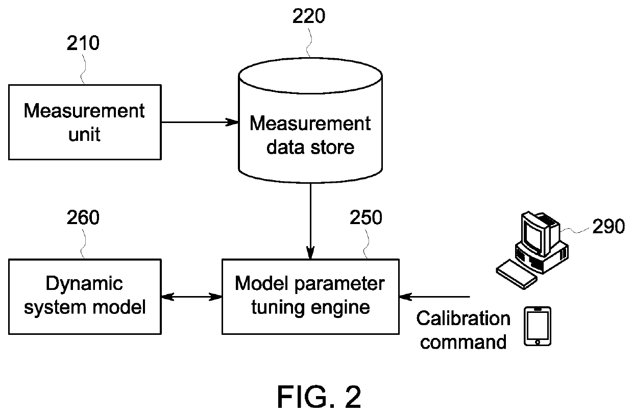
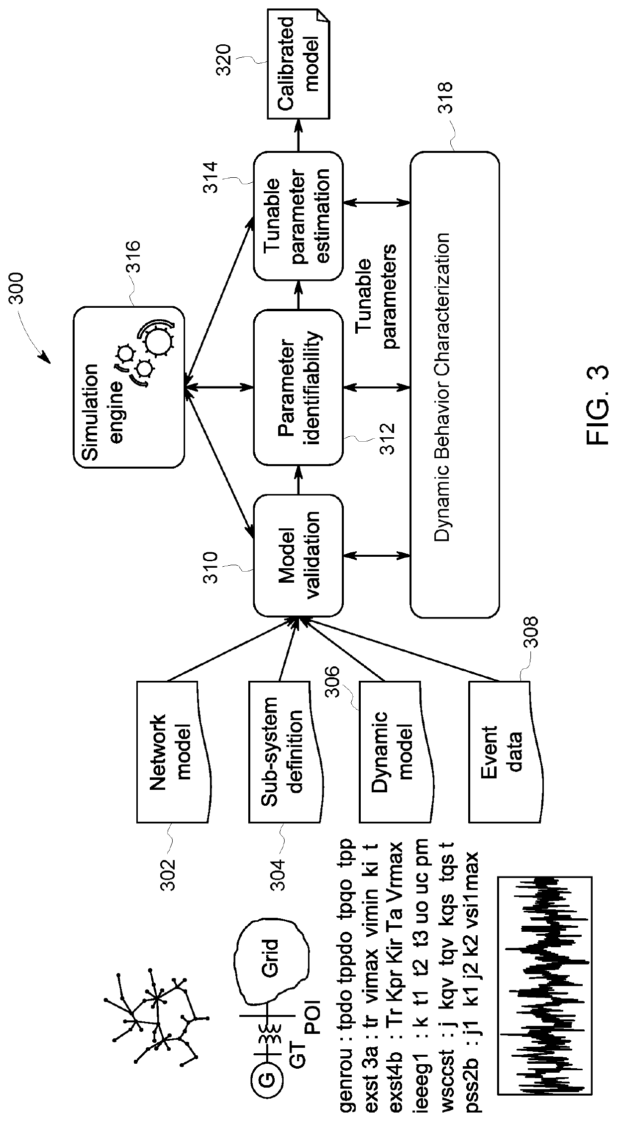
A system for enhanced power system model calibration is provided. The system is programmed to store a model of a device. The model includes a plurality of parameters. The system is also programmed to receive a plurality of events associated with the device, receive a first set of input calibration values for the plurality of parameters, sequentially analyze the plurality of events in a first sequence to determine a set of calibrated parameter values for the model, validate the set of calibrated parameter values for the model to determine fit, and perform Bayesian optimization on the determined fit, the set of calibrated parameter values for the model, and the plurality of events.

Description

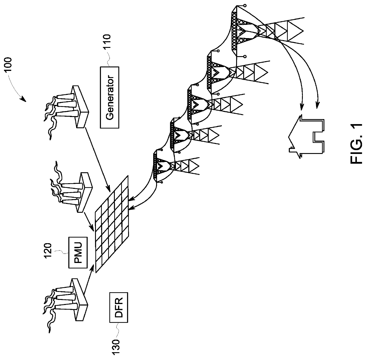
CROSS REFERENCE TO RELATED APPLICATIONS[0001]This application claims the benefit of priority to U.S. Provisional Patent Application No. 62 / 833,492, filed Apr. 12, 2019, entitled “SYSTEMS AND METHODS FOR SEQUENTIAL POWER SYSTEM MODEL PARAMETER ESTIMATION,” the entire contents and disclosure of which are incorporated by reference in its entirety.STATEMENT REGARDING FEDERALLY SPONSORED RESEARCH & DEVELOPMENT[0002]This invention was made with government support under U.S. Government Contract Number: DE-0E0000858 awarded by the Department of Energy. The government has certain rights in the invention.BACKGROUND[0003]The field of the invention relates generally to enhanced power system model calibration, and more particularly, to a system for modeling sequential power systems based on multiple events with Bayesian Optimization.[0004]During the 1996 Western System Coordinating Council (WSCC) blackout, the planning studies conducted using dynamic models had predicted stable system operation,...

Claims


Application Information

Patent Timeline
IPC IPC(8): G06F30/20
CPCG06F2119/06G06F30/20G06F2111/10G06F2113/04G06Q50/06G06F30/18G06F2113/06H02J2203/20Y04S40/20Y02E60/00G06N3/08G06N5/01G06N7/01H02J3/003G06F2111/02G06F7/58H02J3/008G06F17/14
Inventor WANG, HONGGANGMAHAPATRA, KAVERI
Owner GENERAL ELECTRIC CO
Learn More