Keyswitch structure

a keyswitch and keycap technology, applied in the direction of electric switches, contact mechanisms, electrical apparatus, etc., can solve the problems of reducing the stability of the keycap, affecting the yield and production capacity, and increasing the instability of the keycap during the pressing operation, so as to maintain the structural strength of the supports, rotation in a certain degree, and the stability of the pivotal connection. high

Active Publication Date: 2020-10-15
DARFON ELECTRONICS CORP
View PDF0 Cites 2 Cited by
  • Summary
  • Abstract
  • Description
  • Claims
  • Application Information

AI Technical Summary

Benefits of technology

[0005]The present disclosure provides a keyswitch structure, of which supports are connected by a semi-shaft semi-hole engagement, which facilitates the assembly of the supports and can provide a pivotal connection structural strength and action stability in a certain degree.
[0007]Compared with the prior art, the keyswitch structure according to the invention uses an incomplete hole-shaft structure and thereby can maintain the structural strength of the supports. Furthermore, each support has a shaft portion and a shaft recess. By the mutual engagement of the shaft portions and the shaft recesses, the pivotal connection thereof still can maintain the pivotal connection strength and the rotation stability in a certain degree. The two supports of the keyswitch structure according to the invention have the high stable pivotal connection configuration, and can be horizontally and automatically in an end-to-end manner, so that the lifting stroke of the keycap can have better track stability.

Problems solved by technology

For automatic assembly, the above assembly ways make it difficult to adjust process and design jigs, and even to avoid excessively scraping due to misalignment, which also will affect the yield and production capacity.
During a pressing operation on a keyswitch having the two supports, the engagement of the toothed structures will produce engagement and disengagement of the teeth thereof many times, which increases the instability of the keycap of the keyswitch during the pressing operation.
This structural configuration also will reduce the stability of the keycap.
Furthermore, when the whole keyswitch structure is reduced in size, it is difficult for the supports to provide enough space for forming a complete hole-shaft structure.
Even though a complete hole-shaft structure is formed, the structural strength thereof may probably be insufficient, resulting in a reduction of the stability of the pivotal connection of the supports.
Furthermore, in general, a complete hole-shaft structure may cause permanent deformation or damage to the support during assembly.

Method used


Image

  • Keyswitch structure
  • Keyswitch structure
  • Keyswitch structure

Examples


Embodiment Construction

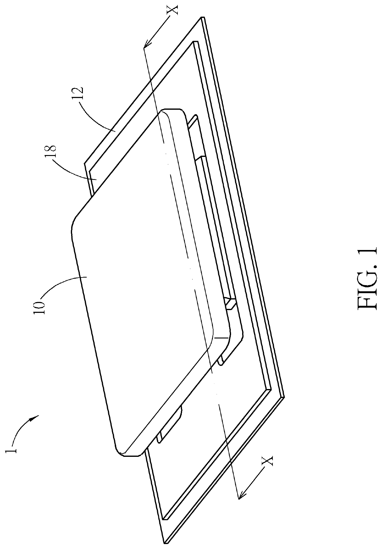
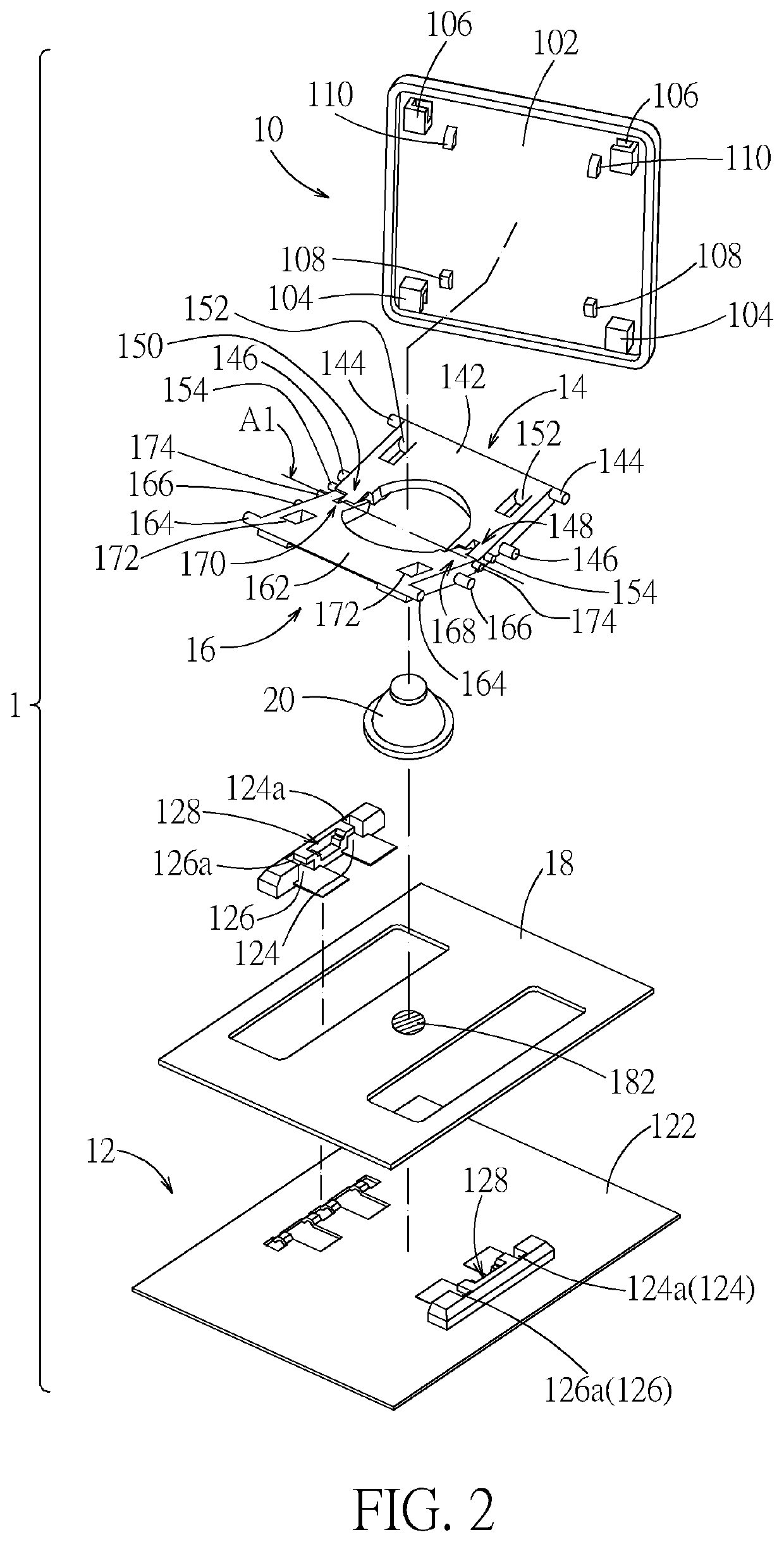
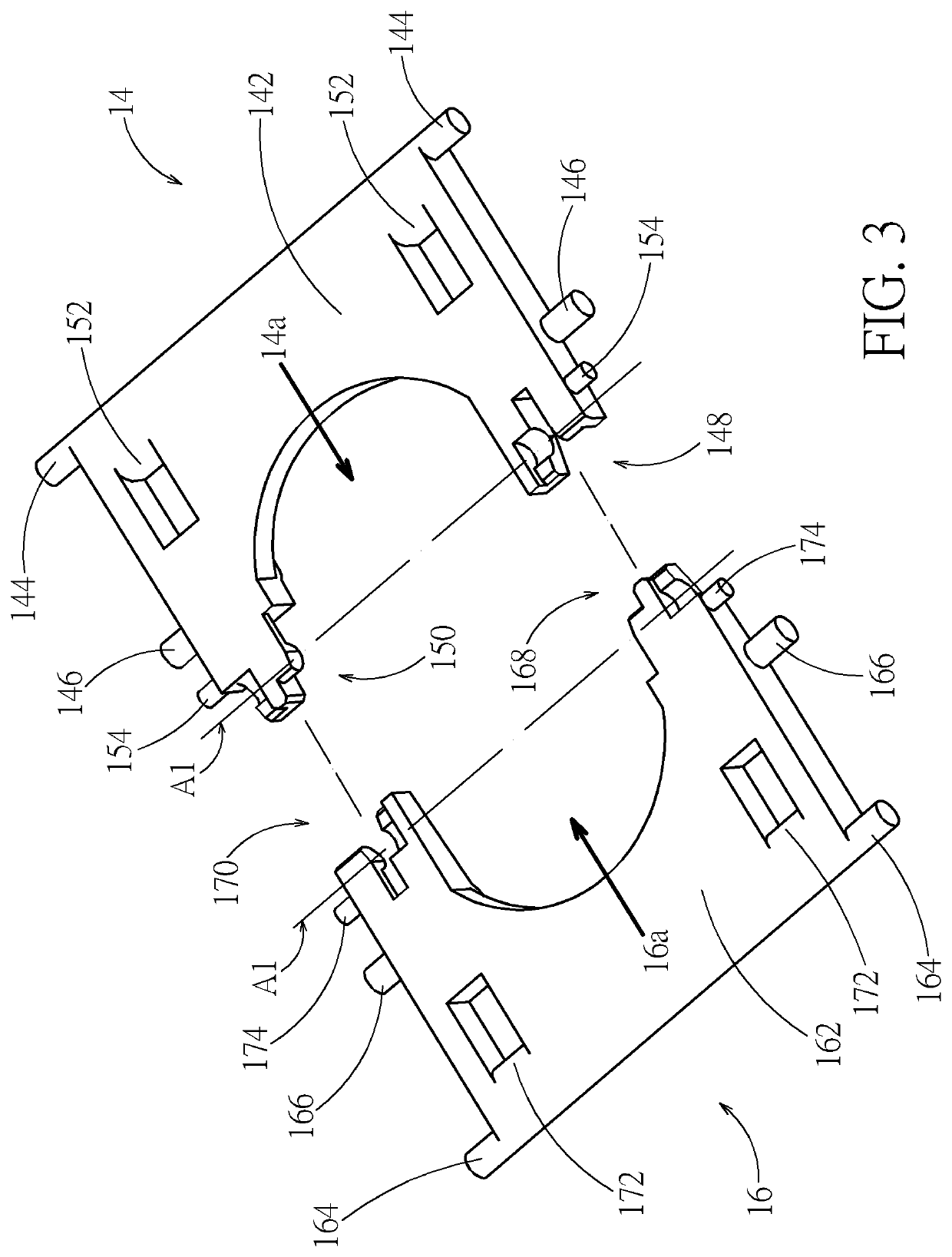
[0025]Please refer to FIG. 1 and FIG. 2. A keyswitch structure 1 according to embodiment includes a keycap 10, a base 12, a first support 14, a second support 16, a switch circuit board 18, and a resilient restoration part 20. The base 12 is disposed under the keycap 10. The first support 14 and the second support 16 are pivotally connected relative to a rotation axis A1 (indicated by a chain line in FIG. 2) and respectively connected to and between the keycap 10 and the base 12. The switch circuit board 18 is placed on the base 12. The resilient restoration part 20 is placed on the switch circuit board 18 corresponding to a switch 182 (indicated by a circle with dashed lines in FIG. 2) of the switch circuit board 18. The keycap 10 can move up and down relative to the base 12 through the first support 14 and the second support 16. When moving down, the keycap 10 can press the resilient restoration part 20 to trigger the switch 182. In practice, the switch circuit board 18 can be but...


PUM


Abstract

A keyswitch structure includes a keycap, a base, and two supports pivotally connected to each other relative to a rotation axis and connected to and between the keycap and the base. One of the supports includes a first shaft recess, a first shaft portion, and a division slot formed therebetween; the other support includes a second shaft recess, a second shaft portion, and a division wall therebetween. The two supports are pivotally connected relative to the rotation axis by the first shaft portion and the second shaft portion rotatably disposed in the first shaft recess and the second shaft recess respectively. Therein, the division wall is inserted into the division slot. The keycap can move up and down relative to the base through the two supports.

Description

BACKGROUND OF THE INVENTION1. Field of the Invention[0001]The present invention relates to a mechanical keyswitch structure, and more particularly to a mechanical keyswitch structure, of which the keycap is supported by and is movable through two supports.2. Description of the Prior Art[0002]Many mechanical keyswitch structures use a scissors support to support its keycap. The two supports of the scissors support are usually pivotally connected through a complete hole and a complete shaft formed at middle portions of the two supports fitting with each other. The hole-shaft fit can provide good relative rotation stability for the supports. However, if the two supports are pivotally connected through a complete hole-shaft structure, the two supports usually need to be assembled together along the pivot axis, or need to cross at a specific angle so as to be assembled. For automatic assembly, the above assembly ways make it difficult to adjust process and design jigs, and even to avoid ...

Claims


Application Information

Patent Timeline
Patent Type & Authority Applications(United States)
IPC IPC(8): H01H13/14
CPCH01H13/14H01H3/125H01H13/705H01H3/122H01H13/10
Inventor CHAO, LING-HSI
Owner DARFON ELECTRONICS CORP
Why Eureka
Try Eureka