
Electrical terminal with resilient contact arm with low insertion force and high normal force

Active Publication Date: 2020-10-15
TYCO ELECTRONICS LOGISTICS AG (CH)
View PDF0 Cites 0 Cited by
  • Summary
  • Abstract
  • Description
  • Claims
  • Application Information

AI Technical Summary

Benefits of technology

The patent describes a method for designing an electrical terminal that has low insertion force and high normal force. This is achieved by deforming a spring arm of the terminal so that it can securely engage with another terminal. The technical effect of this design is to allow for a more reliable and secure connection between electrical terminals.

Problems solved by technology

However, due to the configuration of the tab receptacle terminal, such tab receptacle terminals often have undesirable high insertion forces or undesirably low normal forces, resulting in a large variation of the electrical resistance of the mated terminals when exposed to different environment conditions.
In addition, the spring members of the tab receptacle terminals may yield when mating occurs, causing the mechanical and electrical connection to fail.
These problems are particularly present in smaller connectors which require that the spring members have tighter pitches.
Providing adequate normal force on the contact interfaces for smaller connectors is more difficult.
For power applications, this problem becomes more severe as normal force is inversely proportionate to interface resistance.
Known designs do not provide adequate normal force and therefore presents relatively high changes in resistance after environmental / mechanical conditioning.

Method used


Image

  • Electrical terminal with resilient contact arm with low insertion force and high normal force
  • Electrical terminal with resilient contact arm with low insertion force and high normal force
  • Electrical terminal with resilient contact arm with low insertion force and high normal force

Examples


Embodiment Construction

[0016]The description of illustrative embodiments according to principles of the present invention is intended to be read in connection with the accompanying drawings, which are to be considered part of the entire written description. In the description of embodiments of the invention disclosed herein, any reference to direction or orientation is merely intended for convenience of description and is not intended in any way to limit the scope of the present invention. Relative terms such as “lower,”“upper,”“horizontal,”“vertical,”“above,”“below,”“up,”“down,”“top” and “bottom” as well as derivative thereof (e.g., “horizontally,”“downwardly,”“upwardly,” etc.) should be construed to refer to the orientation as then described or as shown in the drawing under discussion. These relative terms are for convenience of description only and do not require that the apparatus be constructed or operated in a particular orientation unless explicitly indicated as such. Terms such as “attached,”“affi...


PUM


Abstract

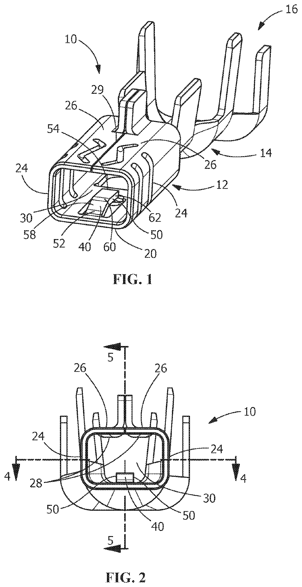
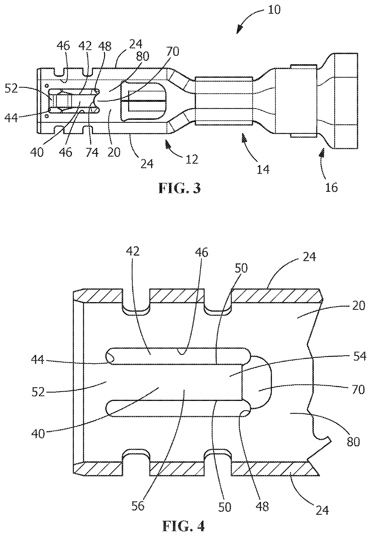
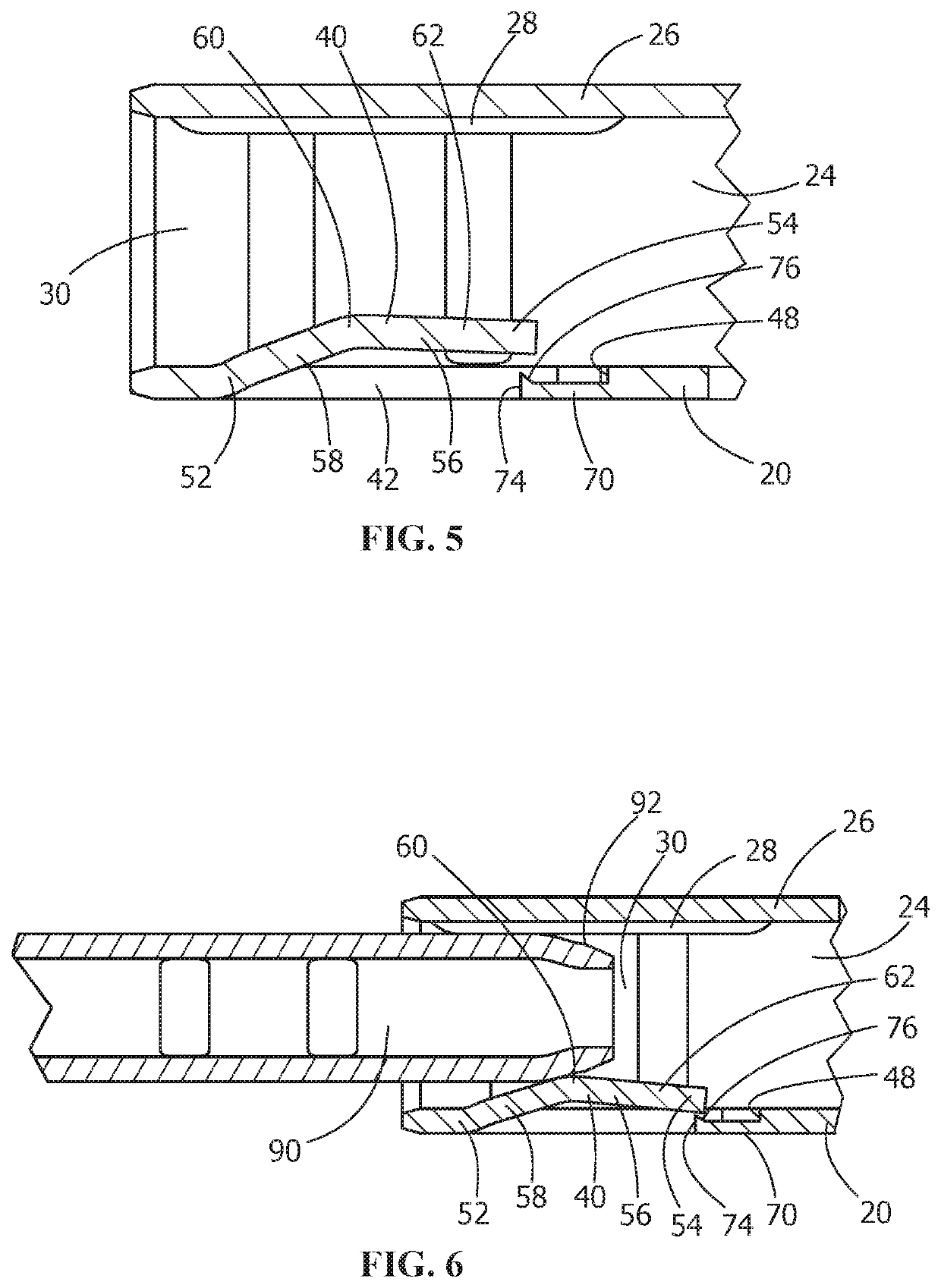
An electrical terminal with a contact portion and a spring arm and a method of insertion. The contact portion has a mating terminal receiving cavity. The spring arm extends from a bottom wall into the mating terminal receiving cavity. The spring arm has a fixed end, a free end and a transition section extending between the fixed end and the free end. The bottom wall has an opening with a front wall and a rear wall. The spring arm extends from the front wall toward the rear wall. A coined area is provided proximate the rear wall of the opening on the bottom wall. The spring arm acts initially as a single supported cantilever beam and then, upon deflection, acts as a double supported beam.

Description

FIELD OF THE INVENTION[0001]The present invention is directed to an electrical terminal with a resilient contact arm with a low insertion force and a high normal force and a method of deforming a spring arm of an electrical terminal to provide low insertion force and high normal force. In particular, the invention is directed to a receptacle terminal which provides sufficient normal force to provide a stable interconnection with a mating terminal to provide a stable electrical resistance regardless of the environmental conditions.BACKGROUND OF THE INVENTION[0002]Socket terminals, such as tab receptacle terminals, which are adapted for quick make and break connections with a mating terminal or mating tab, are known. Terminals of this kind are used to make an electrical connection to a male or tab terminal which is inserted and frictionally held in the socket terminal.[0003]It is often necessary to disconnect and reconnect such terminals a number of times, for example, for testing pur...

Claims


Application Information

Patent Timeline
IPC IPC(8): H01R13/187H01R4/18H01R4/20
CPCH01R4/184H01R13/187H01R4/20H01R13/11
Inventor FAROLE, DOMINIC ANTHONYEMENHEISER, RICHARD BENJAMIN
Owner TYCO ELECTRONICS LOGISTICS AG (CH)
Learn More