Connector structure of ink pouch

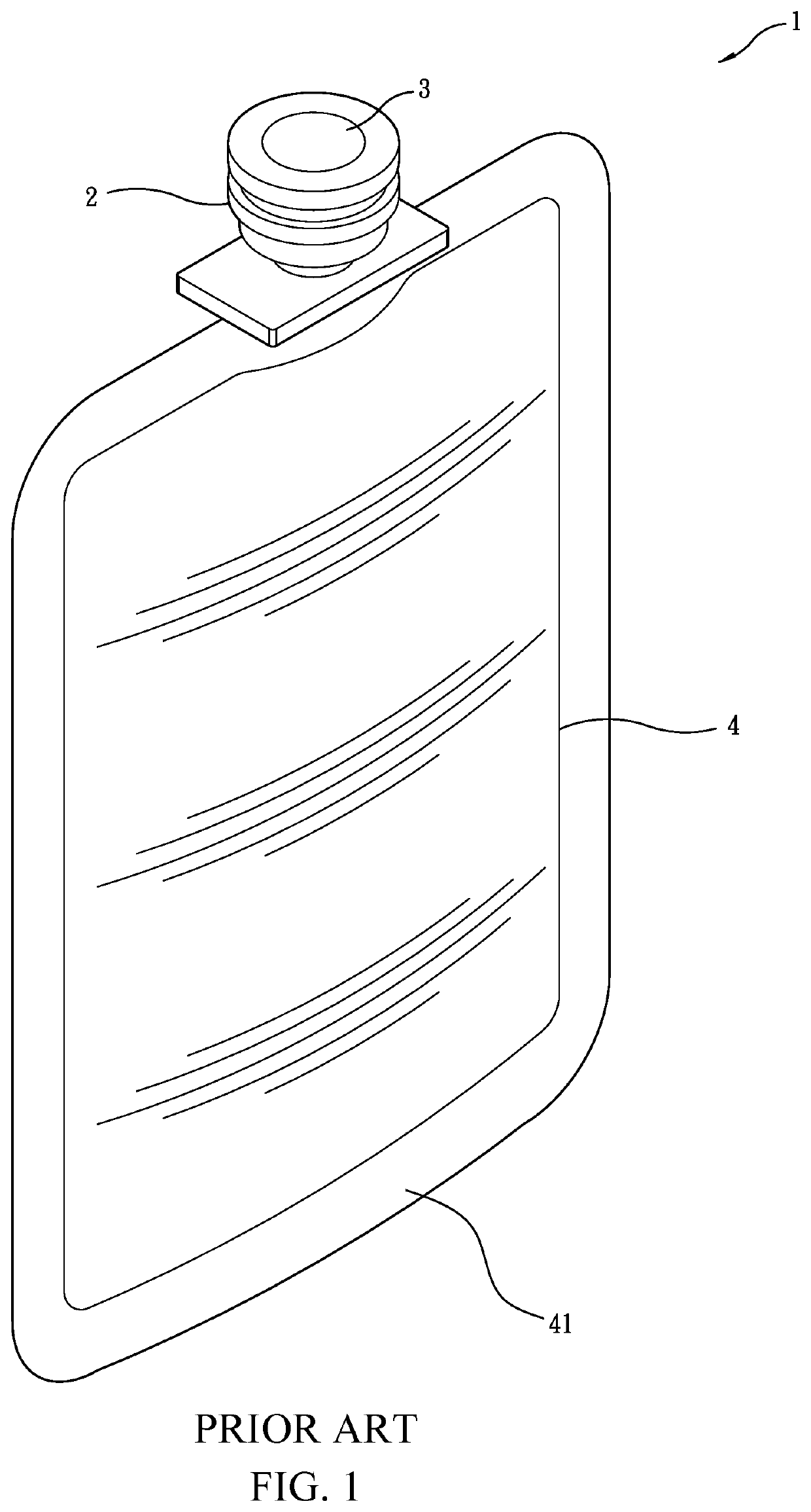
a technology of connecting structure and ink pouch, which is applied in the field of ink pouches, can solve the problems of changing the quality of ink, leaking of ink, and the inability to fix the amount of ink in the pouch body b>4/b>, and achieves the effects of reducing costs, facilitating fabrication, and high fabrication cos

Active Publication Date: 2020-10-22
TAIWAN NANOTECH CORP
View PDF0 Cites 0 Cited by
  • Summary
  • Abstract
  • Description
  • Claims
  • Application Information

AI Technical Summary

Benefits of technology

[0005]In view of the above, in order to overcome the drawbacks of the known techniques that a known connector structure of an ink pouch suffers being difficult to set a predetermined amount of ink filled therein, ink filled therein being ready to change quality, and fabrication cost being high, the present invention provides a connector structure of an ink pouch, which generally comprises: a connector body, which comprises a joining section, a sealing section joined to the joining section, and an ink passage extending in a longitudinal direction through the joining section and the sealing section, the sealing section having a top surface on which a fitting peg, which is hollow, is formed to extend upward from a circumference of the ink passage, the top surface of the sealing section being formed with a plurality of insertion slots that are extended downward and spaced from each other along a circumference of the fitting peg by a predetermined interval, the sealing section having an external circumferential surface that is partly and inwardly recessed to form an annular retaining groove, the annular retaining groove being in communication with ends of the plurality of the insertion slots; a sealing cap having a top surface that is partly recessed downward in a central portion thereof to form a pressing section, the sealing cap having a bottom surface that is partly recessed upward to form a fitting trough corresponding in position to the pressing section, the bottom surface of the sealing cap being provided with a plurality of engaging and retaining sections projecting therefrom and along a circumference of the fitting trough and spaced from each other by a predetermined interval, the engaging and retaining sections each comprising an insertion arm extending downward from the bottom surface of the sealing cap and an engaging block protruding outward from an end of the insertion arm; and a flexible plug having an outside diameter that is greater than an inside diameter of the ink passage of the connector body. To combine, the flexible plug is positioned in the fitting trough of the sealing cap, and the insertion arms of the engaging and retaining sections of the sealing cap are respectively inserted into the insertion slots of the connector body, such that the engaging blocks protrude into the annular retaining groove of the connector body to securely combine the sealing cap and the connector body together. The fitting peg is located in the fitting trough and the flexible plug closes the ink passage. As such, the present invention provides effects of being securely and tightly combined to prevent leaking, enabling filling of ink of a fixed amount, protecting ink from quality variation resulting from heating, enabling easy fabrication, lowering costs, and having enhanced market competition power.

Problems solved by technology

The rubber plug is readily movable due to an external force acting thereon and consequently, leaking of ink occurs.
As such, the amount of ink filled in the pouch body 4 cannot be made fixed, and it also happens that a high temperature caused by the high-frequency bonding changes the quality of the ink.
Further, such a process of two injection molding operations is carried out with specific machinery and molds and this increases the cost of fabrication.

Method used


Image

  • Connector structure of ink pouch
  • Connector structure of ink pouch
  • Connector structure of ink pouch

Examples


Embodiment Construction

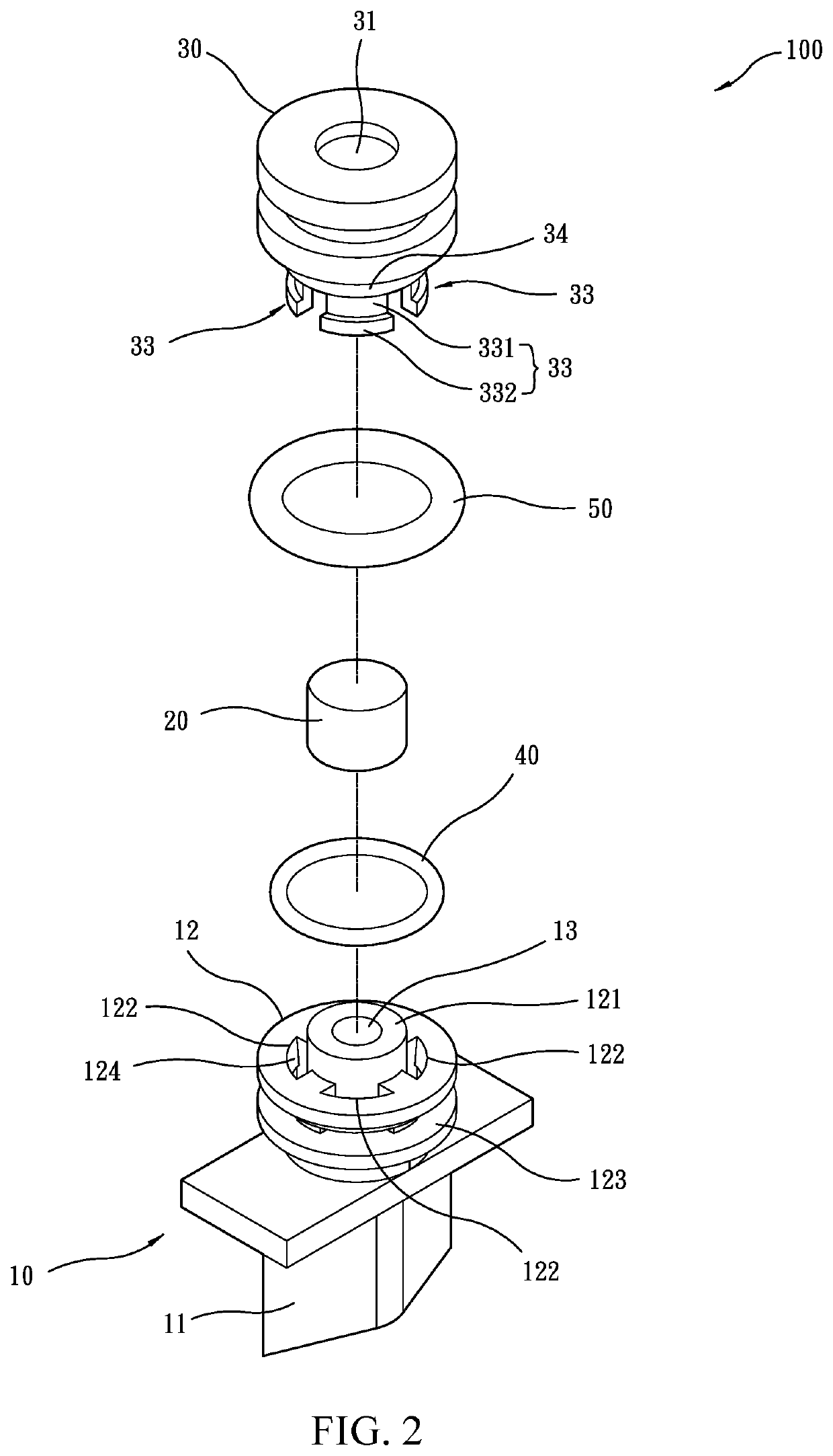
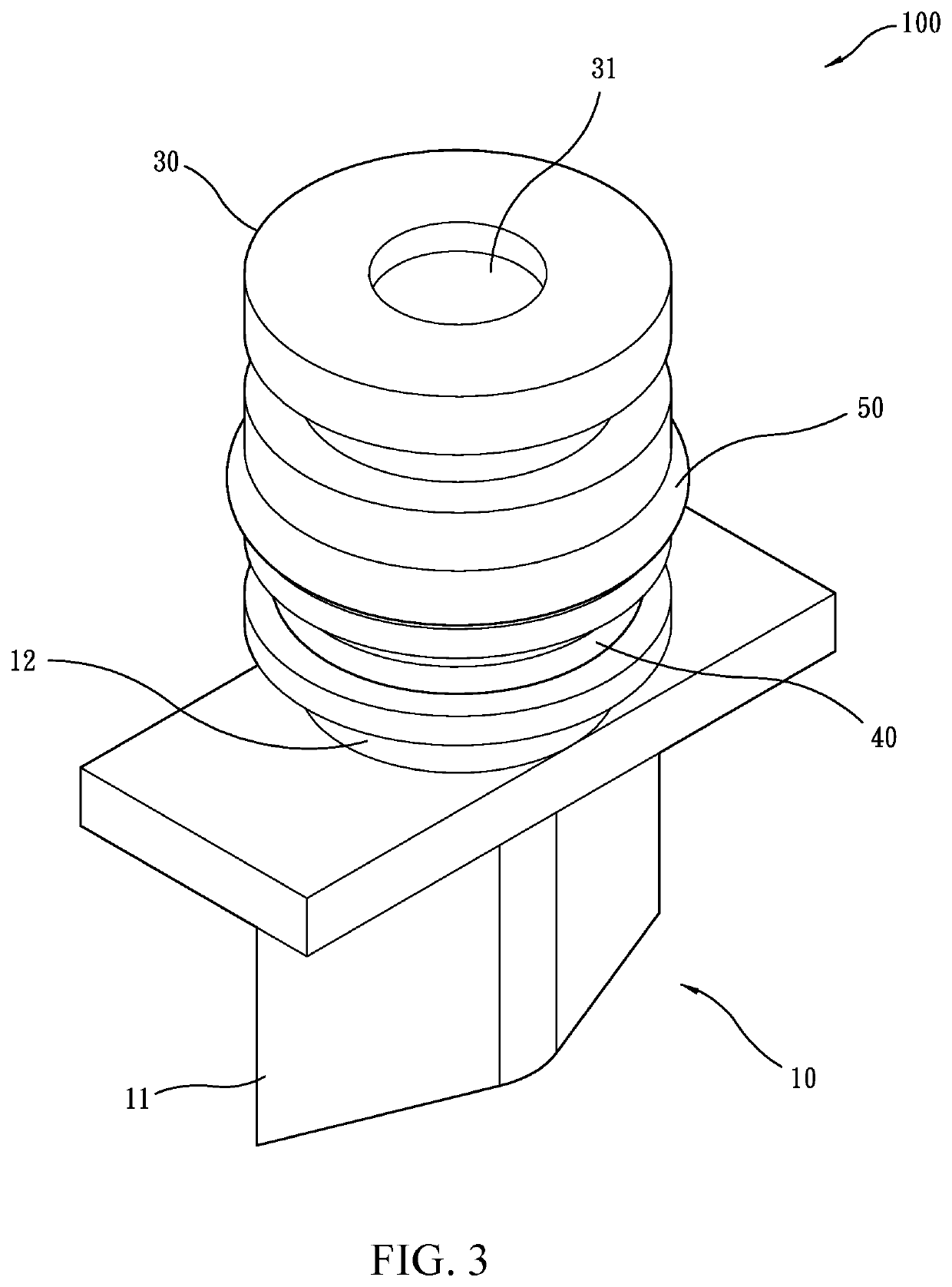
[0011]Referring to FIGS. 2-8, a preferred embodiment of the present invention is shown, providing a connector structure 100 of an ink pouch, generally comprising a connector body 10, a flexible plug 20, a sealing cap 30, a first sealing ring 40, and a second sealing ring 50.

[0012]Referring to FIGS. 2-4, the connector body 10 is integrally formed of plastics. The connector body 10 includes a joining section 11, a sealing section 12 integrally combined with the joining section 11, and an ink passage 13 extending in a longitudinal direction through the joining section 11 and the sealing section 12. The joining section 11 is provided for connection with and combined with a pouch body. The sealing section 12 is generally of a cylindrical configuration. The sealing section 12 has a top surface on which a fitting peg 121, which is hollow, is formed to extend upward from a circumference of the ink passage 13. The top surface of the sealing section 12 is formed with a plurality of insertion ...


PUM

PropertyMeasurementUnit
circumferenceaaaaaaaaaa
diameteraaaaaaaaaa
flexibleaaaaaaaaaa

Abstract

A connector structure of an ink pouch includes a connector body including a joining section, a sealing section, and an ink passage extending through the joining section and the sealing section, the sealing section having a hollow fitting peg, insertion slots, and an annular retaining groove in communication with the insertion slots; a sealing cap including a pressing section and a fitting trough corresponding in position to the pressing section and engaging and retaining sections, each of which has an insertion arm and an engaging block protruding from the insertion arm; and a flexible plug. To combine, the flexible plug is positioned in the fitting trough and the insertion arms of the engaging and retaining sections are inserted into the insertion slots to have the engaging blocks protrude into the annular retaining groove. The fitting peg is received in the fitting trough and the flexible plug closes the ink passage.

Description

TECHNICAL FIELD OF THE INVENTION[0001]The present invention relates to an ink pouch, and more particularly to a connector structure of an ink pouch.DESCRIPTION OF THE PRIOR ART[0002]The term “ink pouch” as used here refers to a pouch or a bag or a flexible container that receives and holds an amount of ink in an interior space thereof and is directly connectable to a printer or is mountable in an ink cartridge to supply ink to a printer.[0003]An early-day ink pouch was structured to include a rubber plug in an ink channel. The rubber plug is readily movable due to an external force acting thereon and consequently, leaking of ink occurs.[0004]Taiwan Patent No. 1462841 discloses an ink pouch connector structure 1, which effectively overcomes the issue of ink leaking, wherein as shown in FIG. 1, two injection molding operations are carried out to first forming an enclosing arrangement of a connector 2 and a flexible rubber material 3, and then to have the connector 2 bonded to a pouch ...

Claims


Application Information

Patent Timeline
Patent Type & Authority Applications(United States)
IPC IPC(8): B41J2/175
CPCB41J2002/17516B41J2/1754B41J2/17513B41J2/17553B41J2/17506B41J2/17523B65D75/5883B41J2/17503
Inventor HSIEH, CHENG-YANG
Owner TAIWAN NANOTECH CORP
Why Eureka
Try Eureka