Fishing Hook Guide and Float Deflector

a technology of float deflector and fishing hook, which is applied in the direction of fish hooks, fishing, animal husbandry, etc., can solve the problems of loss of flotation, improper weight, and many problems in the design of the previous design

Active Publication Date: 2020-10-29
FOWLER DAVID WAYNE +1
View PDF0 Cites 1 Cited by
  • Summary
  • Abstract
  • Description
  • Claims
  • Application Information

AI Technical Summary

Problems solved by technology

Apparatus designs for protecting fishing hooks, bait, and bystanders while fishing are known; however, previous designs are plagued by many problems.
Among these problems are improper weight, loss of flotation due to damage, and improper shape leading to entanglement and bait lodging.

Method used


Image

  • Fishing Hook Guide and Float Deflector
  • Fishing Hook Guide and Float Deflector
  • Fishing Hook Guide and Float Deflector

Examples


Embodiment Construction

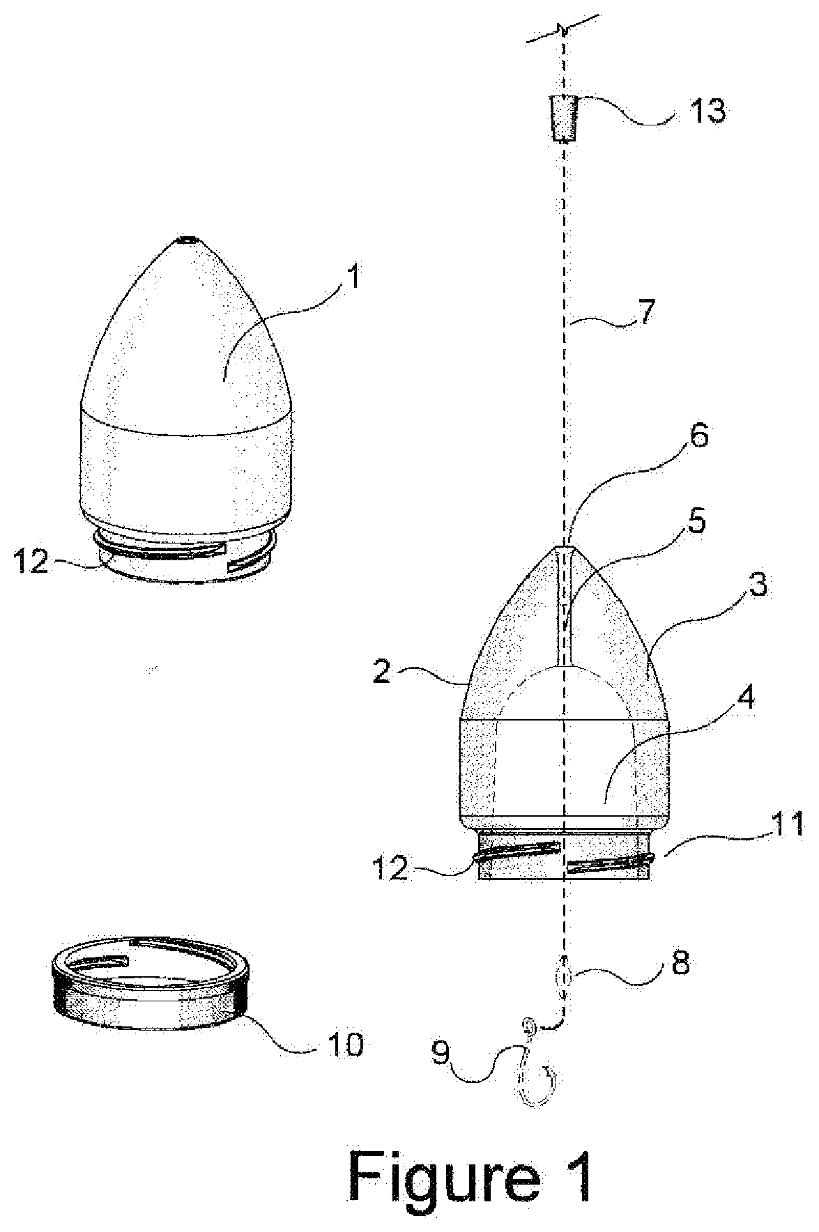
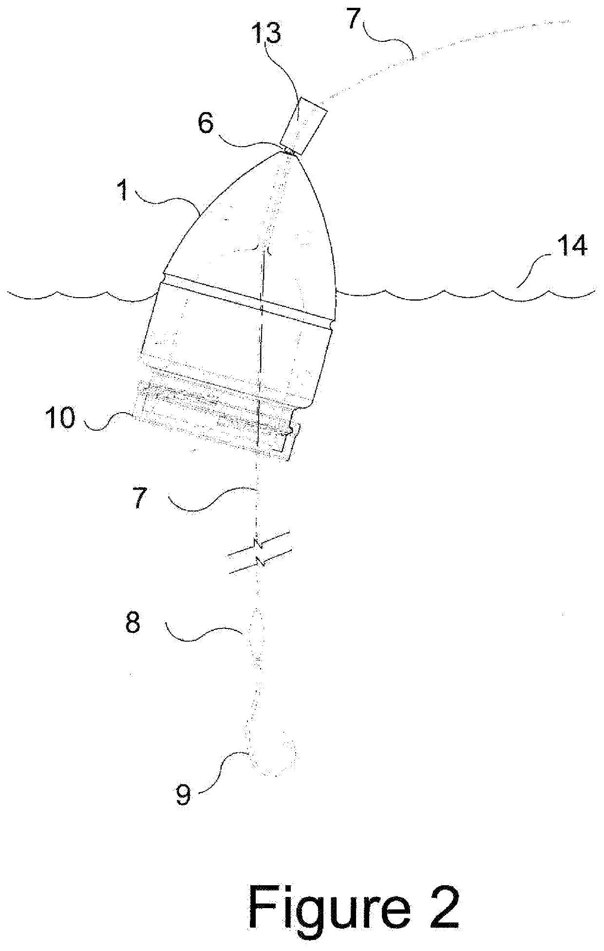
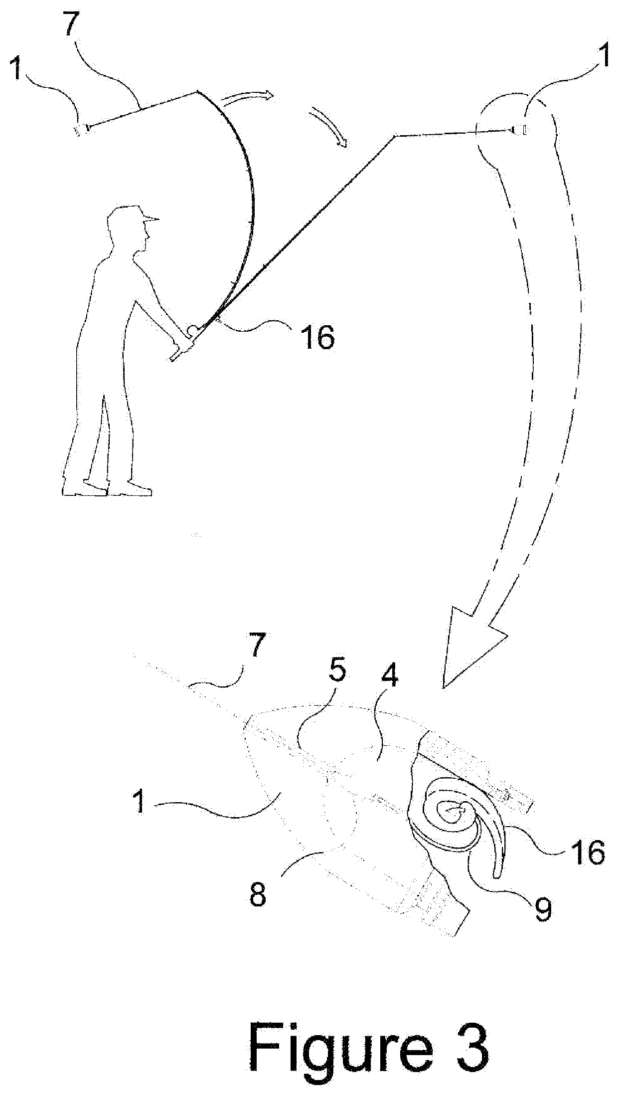
[0014]Referring to the figures, and more specifically to FIG. 1), it can be seen that the fishing hook guard and float detector 1 is essentially in the shape of a bullet or swollen cone. The outer cover 2 is constructed of plastic, aluminum or some other such lightweight, rigid material. The interior of the cone 1 is filled with a lightweight filler 3 such as Styrofoam. The lightweight filler 3 provides buoyancy, allowing the fishing hook guard and float detector to be used as a float or bobber for fishing. A suitably shaped and sized cavity 4 is formed within the filler material. A line passage tunnel 5 is formed from the top of the cavity 4 to the tip of the cone 6. Fishing line 7 is passed down through tunnel 5, and beyond cavity 4, where it is connected to sinker weight 8 and fishing hook 9. A jar lid-shaped bottom cap 10 may be screwed onto the bottom aperture 11 of cone 1 by way of coarse cap threads 12. As the fishing hook guard and float detector comes to rest, floating on t...


PUM


Abstract

An apparatus for protecting fishermen from bait loss, entanglement of fishing rigs during casting and reel-in, and injury to fellow fishermen and bystanders. The apparatus consists of a hook enclosing float that will contain the hook and bait during casting and reel-in and release the hook to a specified depth while floating on the water.

Description

CROSS-REFERENCE TO RELATED APPLICATIONS[0001]U.S. Pat. No. 6,691,448 B2 to JonesU.S. Pat. No. 5,452,538 A to TrefiakU.S. Pat. No. 3,224,134 A to HolcombeU.S. Pat. No. 4,817,327 A to DeKayUS Patent number US20070294934 A1 to James MyersUS Patent number US20130283669 A1 to Joaquim da Rosa, Casey DavidsonBACKGROUND OF THE INVENTION[0002]Fishing is one of man's oldest endeavors. Whether it be a commercial enterprise or a recreational experience, as in other endeavors, safety and ease of operation are a paramount concern. Fishing has almost always been done with the employment of a sharp hook. This brings about the possibility of injury to fingers, eyes, ears and just about every part of the fisherman's body. This has become of even greater concern as more and more people, and especially children, partake in the sport of fishing. The process of casting a hook from a fishing rod requires a large area: often too large for the safety of other participants. The whipping about of a sharp, exp...

Claims


Application Information

Patent Timeline
Patent Type & Authority Applications(United States)
IPC IPC(8): A01K83/00A01K85/10
CPCA01K85/02A01K85/10A01K83/00
Inventor FOWLER, DAVID WAYNEFOWLER, RICKY GRANT
Owner FOWLER DAVID WAYNE
Why Eureka
Try Eureka