X-ray phase imaging apparatus

a phase imaging and x-ray technology, applied in imaging devices, applications, instruments, etc., can solve the problems of large area, unintended gap generation between the plurality of gratings adjacent to each other, and difficult to accurately produce a single grating having a large area

Active Publication Date: 2020-10-29
SHIMADZU CORP
View PDF0 Cites 13 Cited by
  • Summary
  • Abstract
  • Description
  • Claims
  • Application Information

AI Technical Summary

Benefits of technology

[0011]The present invention has been made to solve the above-mentioned problems, and an object of the present invention is to provide an X-ray phase imaging apparatus capable of enlarging an area in a direction perpendicular to a direction in which a subject and an imaging system are relatively moved while suppressing occurrence of a portion where the subject cannot be imaged due to occurrence of a portion in which the subject hardly passes through the grating in a configuration in which imaging is performed while relatively moving the subject and the imaging system.
[0014]With this, in the grating composed of the plurality of grating portions, it is possible to suppress the occurrence of a portion in which the subject hardly passes through the grating in the third direction in which the plurality of grating portions are arranged side by side when performing imaging while relatively moving the subject and the imaging system in the first direction. As a result, in the configuration in which imaging is performed while relatively moving the subject and the imaging system, it is possible to increase an area in a direction perpendicular to a direction in which the subject and the imaging system are relatively moved while suppressing the occurrence of a portion in which the subject cannot be imaged due to the occurrence of a portion in which the subject hardly passes through the grating.

Problems solved by technology

Note that a grating used in a conventional X-ray phase imaging apparatus as disclosed in Japanese Unexamined Patent Application Publication No. 2017-44603 has a large aspect ratio (the height (depth) of the grating relative to the grating pitch), so it is difficult to accurately produce a single grating having a large area.
As described above, when a plurality of gratings is arranged side by side, it is conceivable that the plurality of gratings is bonded to each other, but since the plurality of gratings is manufactured as separate members from each other, an unintended gap may be generated between the plurality of gratings adjacent to each other due to a manufacturing error.
Therefore, as disclosed in the X-ray phase imaging apparatus of Japanese Unexamined Patent Application Publication No. 2017-44603, in a configuration in which imaging is performed while relatively moving a subject and an imaging system, when a plurality of gratings is arranged side by side in order to increase the area in a direction perpendicular to a direction along which the subject and the imaging system are relatively moved, there may be a problem that a portion where the subject cannot be imaged is generated because a portion in which the subject hardly passes through the grating is generated.

Method used


Image

  • X-ray phase imaging apparatus
  • X-ray phase imaging apparatus
  • X-ray phase imaging apparatus

Examples


embodiment 1

Effects of Embodiment 1

[0099]In the device of the first embodiment, the following effects can be obtained.

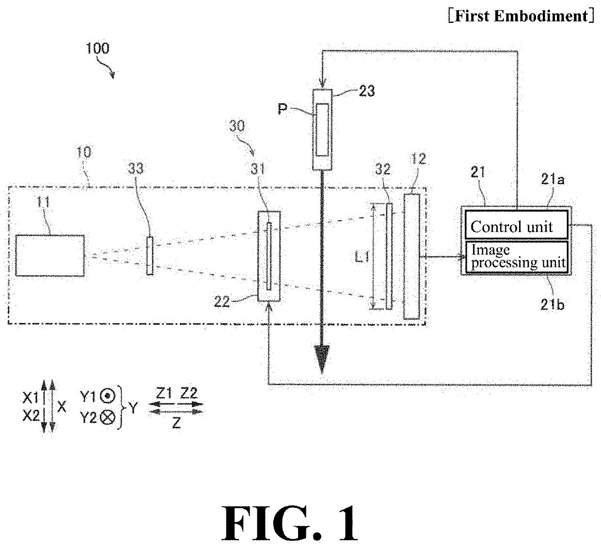
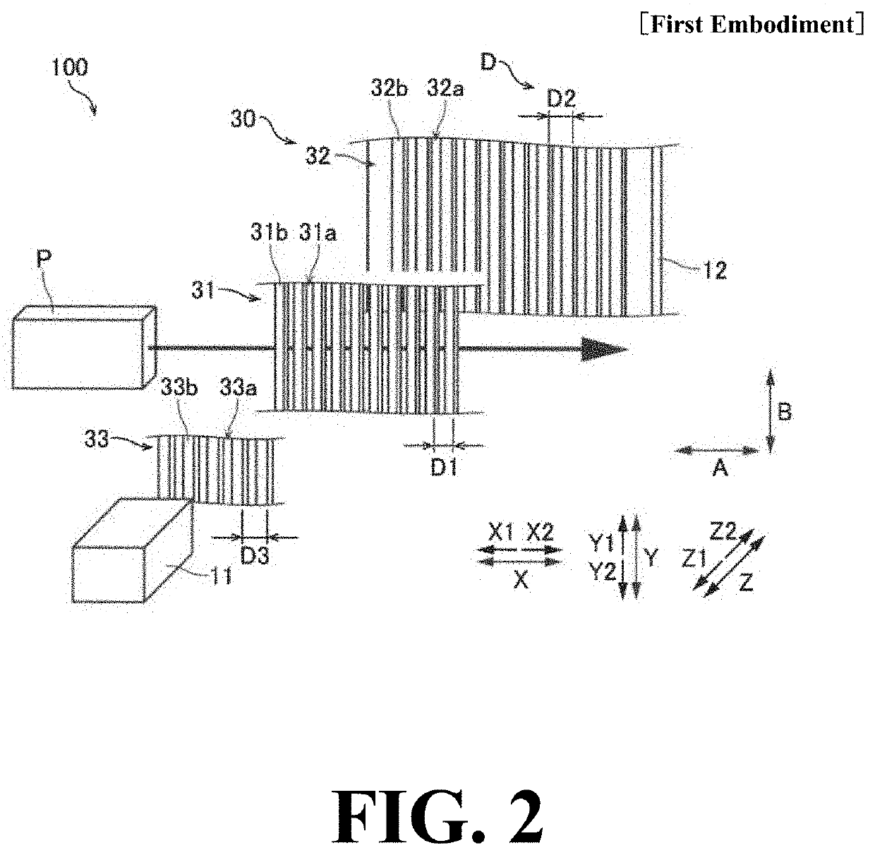
[0100]In the first embodiment, as described above, at least one of the plurality of gratings 30 (the first grating 31 and the second grating 32) is composed of the plurality of grating portions 30c arranged side by side along a third direction (Y-direction) perpendicular the first direction (X-direction) in which the subject P or the imaging system 10 is moved by the subject moving mechanism 23 and the second direction (Z-direction) in which the X-ray tube 11, the detection unit 12, and the plurality of gratings 30 are arranged, and the plurality of grating portions 30c are arranged such that adjacent grating portions 30c overlap each other when viewed in the first direction.

[0101]As a result, it is possible to suppress the occurrence of a portion in which the subject P hardly passes through the grating 30 in the third direction in which the plurality of grating portions 30c is ...

embodiment 2

Effects of Embodiment 2

[0121]In the second embodiment, the following effects can be obtained.

[0122]In the second embodiment, as described above, the subject moving mechanism 23 is configured to move the subject P or the imaging system 10 along the direction (B-direction) in which the gratings of the plurality of gratings 230 extend, and the plurality of grating portions 230c is arranged side by side along the arc such that at least one of the gratings 230 (the first grating 231 and the second grating 232) composed of the plurality of grating portions 230c has a convex arc shape on the detection unit 12 side (the Z2-side) as viewed in the first direction (X-direction).

[0123]This makes it possible to suppress oblique incidence (oblique incidence) of X-rays in all of the plurality of grating portions 230c arranged side by side along the third direction (Y-direction) as compared with when the plurality of grating portions 230c is arranged substantially linearly as viewed in the first di...

embodiment 3

Effects of Embodiment 3

[0133]In the third embodiment, the following effects can be obtained.

[0134]In the third embodiment, as described above, the plurality of grating portions 330c are arranged such that the columns C composed of the plurality of grating portions 330c arranged adjacent to each other along the third direction (Y-direction) are arranged in at least two columns along the first direction (X-direction), and the grating portions 330c of the columns C adjacent in the first direction are arranged in the third direction to each other, so that the plurality of grating portions 330c is arranged in a zigzag manner as viewed in the second direction (Z-direction), whereby the adjacent grating portions 330c overlap each other as viewed in the first direction.

[0135]As a result, it is possible to easily make the adjacent grating portions 330c overlap when viewed in the first direction by the plurality of grating portions 330c arranged in a zigzag shape when viewed in the second dir...


PUM

PropertyMeasurementUnit
angleaaaaaaaaaa
phase-aaaaaaaaaa
phaseaaaaaaaaaa

Abstract

In this X-ray phase imaging apparatus, at least one of a plurality of gratings is composed of a plurality of grating portions arranged along a third direction perpendicular to a first direction along which a subject or an imaging system is moved by a moving mechanism and a second direction along which an X-ray source, a detection unit, and a plurality of grating portions are arranged. The plurality of grating portions are arranged such that adjacent grating portions overlap each other when viewed in the first direction.

Description

CROSS-REFERENCE TO THE RELATED APPLICATIONS[0001]The priority application number JP2019-082459, entitled “X-ray phase imaging apparatus”, filed on Apr. 24, 2019, and invented by Satoshi Sano, Koichi Tanabe, Yukihisa Wada, Satoshi Tokuda, Akira Horiba, and Naoki Morimoto, upon which this patent application is based is hereby incorporated by reference.BACKGROUND OF THE INVENTIONField of the Invention[0002]The present invention relates to an X-ray phase imaging apparatus, and more particularly to an X-ray phase imaging apparatus for performing imaging while relatively moving a subject and an imaging system.Description of the Background Art[0003]Conventionally, an X-ray phase imaging apparatus for performing imaging while relatively moving a subject and an imaging system is known. Such an X-ray phase imaging apparatus is disclosed, for example, in Japanese Unexamined Patent Application Publication No. 2017-44603.[0004]The Japanese Unexamined Patent Application Publication No. 2017-44603...

Claims


Application Information

Patent Timeline
Patent Type & Authority Applications(United States)
IPC IPC(8): A61B6/00G01N23/20
CPCA61B6/4291A61B6/484G01N23/20075G01N23/041A61B6/4035A61B6/0487G01N2223/1016G01N2223/3303G01N2223/427G01N2223/3307A61B6/4435G21K2207/005G21K1/06
Inventor SANO, SATOSHITANABE, KOICHIWADA, YUKIHISATOKUDA, SATOSHIHORIBA, AKIRAMORIMOTO, NAOKI
Owner SHIMADZU CORP
Why Eureka
Try Eureka