
Automated fiber placement roller

Active Publication Date: 2020-10-29
THE BOEING CO
View PDF0 Cites 0 Cited by
  • Summary
  • Abstract
  • Description
  • Claims
  • Application Information

AI Technical Summary

Benefits of technology

The patent describes a method for automated composite layup that involves applying heat to a portion of a workpiece and then using a roller to press tows onto that portion of the workpiece while cooling the roller to prevent charring. The method is done using a fiber placement machine with a heat source. This technology allows for precise placement of fiber tows onto the workpiece, improving the quality and efficiency of the composite layup process.

Problems solved by technology

However, polymer-based rollers do not last long when the polymer-embedded fiber material uses a thermoplastic polymer because temperatures used to soften the thermoplastic polymer tend to soften the roller, which can significantly reduce the useful life of the roller.
Losing contact in this way can result in the fiber tows 114 in that region not contacting underlying layers or not adhering properly to the underlying layers.

Method used


Image

  • Automated fiber placement roller
  • Automated fiber placement roller
  • Automated fiber placement roller

Examples


Embodiment Construction

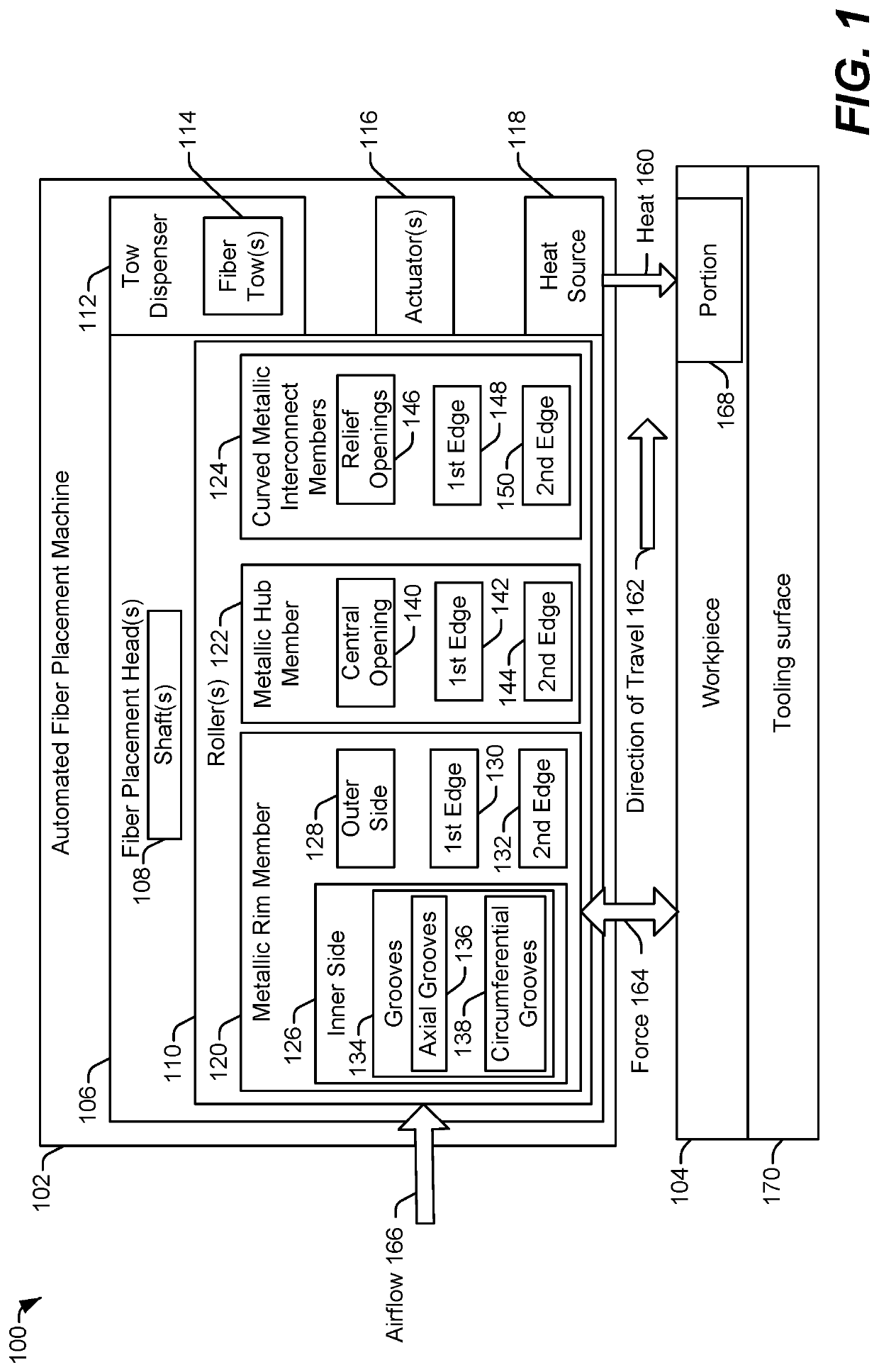
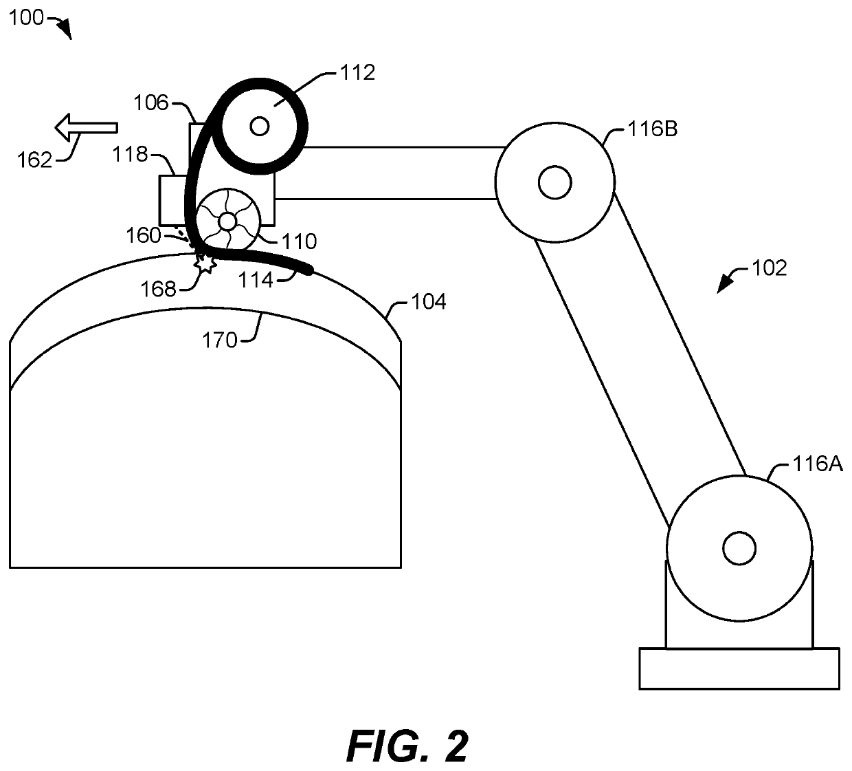
[0012]Particular implementations are described herein with reference to the drawings. In the description, common features are designated by common reference numbers throughout the drawings. In some drawings, multiple instances of a particular type of feature are used. Although these features are physically and / or logically distinct, the same reference number is used for each, and the different instances are distinguished by addition of a letter to the reference number. When the features as a group or a type are referred to herein (e.g., when no particular one of the features is being referenced), the reference number is used without a distinguishing letter. However, when one particular feature of multiple features of the same type is referred to herein, the reference number is used with the distinguishing letter. For example, referring to FIG. 2, multiple actuators 116A and 116B are shown. When referring to a particular one of these actuators, such as the actuator 116A, the distingu...


PUM


Abstract

An automated fiber placement roller includes a metallic rim member arranged about a central axis and having an inner side and an outer side. The central axis is closer to the inner side than to the outer side, and the inner side defines a plurality of grooves enabling elastic deformation of the metallic rim member responsive to a force applied to the outer side. The automated fiber placement roller also includes a metallic hub member arranged substantially concentric with the metallic rim member about the central axis. The metallic hub member defines an opening to receive a shaft of an automated fiber placement machine. The automated fiber placement roller further includes a plurality of curved metallic interconnect members extending between the metallic hub member and the metallic rim member. Each of the plurality of curved metallic interconnect members is elastically deformable responsive to the force applied to the outer side.

Description

FIELD OF THE DISCLOSURE[0001]The present disclosure is generally related to automated fiber placement for composite layup.BACKGROUND[0002]Composite layup involves forming layers of polymer-embedded fiber material into a specified shape to form an object. The polymer-embedded fiber material can be positioned manually or can be positioned automatically using an automated fiber placement machine. An automated fiber placement machine usually places the polymer-embedded fiber material as strips of material referred to as tows or fiber tows. A roller of the automated fiber placement machine rolls over each tow to press it into place on a tooling surface or on a previously placed layer to form the specified shape.[0003]After one or more layers of the polymer-embedded fiber material are positioned as desired, a polymer of the polymer-embedded fiber material is hardened to secured the polymer-embedded fiber material in position. When the polymer includes a thermoset polymer, the polymer is u...

Claims


Application Information

Patent Timeline
IPC IPC(8): B29C70/38
CPCB29C70/384B29C64/118B33Y10/00B33Y30/00B29C64/218
Inventor LA GORCE, ADAM
Owner THE BOEING CO
Features
  • Generate Ideas
  • Intellectual Property
  • Life Sciences
  • Materials
  • Tech Scout
  • Unparalleled Data Quality
  • Higher Quality Content
  • 60% Fewer Hallucinations
Learn More