Composite spacer fabric

a spacer fabric and composite technology, applied in the field of spacer fabrics, can solve the problems of only extremely low stretchability in the production (knitting) and transverse directions of the opposing cover layer, and achieve the effects of good shapability of the spacer fabric, good stretchability, and reduced deformation

Pending Publication Date: 2020-10-29
MULLER TEXTIL
View PDF1 Cites 7 Cited by
  • Summary
  • Abstract
  • Description
  • Claims
  • Application Information

AI Technical Summary

Benefits of technology

[0023]The structuring can also help for example to improve the ventilation of an occupant when used on a vehicle seat. Outer of all, a certain air transport along the compressed areas can be achieved through the three-dimensional structure. However, the composite can particularly preferably also be combined with active ventilation of an air-conditioning seat.
[0061]And despite the formation of the openings to achieve the least possible stretch in the production and transverse directions, according to a particularly preferred embodiment of the invention on the one hand the yarns of the second yarn system alternately form pillar stitches along the production direction and on the other hand form stitches formed from the group of tricot, cord, satin, velvet, and atlas. The stitches selected from the group of tricot, cord, satin, velvet, and satin connect the individual stitch wales in the transverse direction so that there is little stretchability in the transverse direction. However, if the yarns of the second yarn system, that is to say the first partial yarn system and the complementary second partial yarn system, also form pillar stitches, the tensile strength in the production direction is further increased and the stretchability is also reduced.

Problems solved by technology

While one of the two warp-knitted fabric layers is quite stretchy in the production direction and transverse direction, the opposite cover layer has only an extremely low stretchability in the production (knitting) and transverse directions.

Method used


Image

  • Composite spacer fabric
  • Composite spacer fabric
  • Composite spacer fabric

Examples


Embodiment Construction

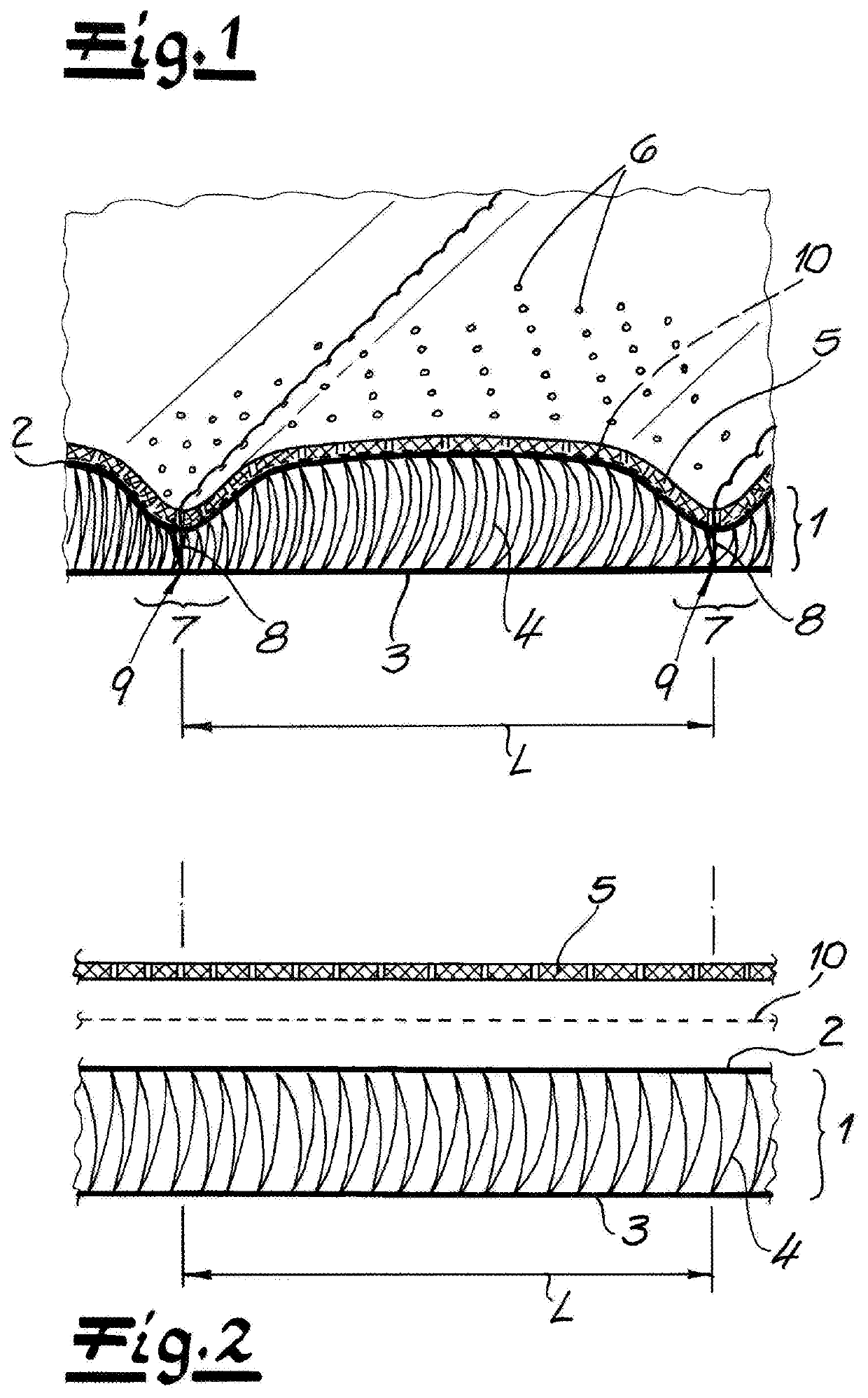
[0076]FIG. 1 shows a composite that forms the uppermost layers of a vehicle seat, for example a car seat. The composite comprises a spacer fabric 1 that, as usual, extends along a production direction P and a transverse direction Q perpendicular to it. The embodiment of the spacer fabric 1 is further explained below with reference to the production direction P and the transverse direction Q. The production direction P is also referred to as the knitting direction or the longitudinal direction due to the production method.

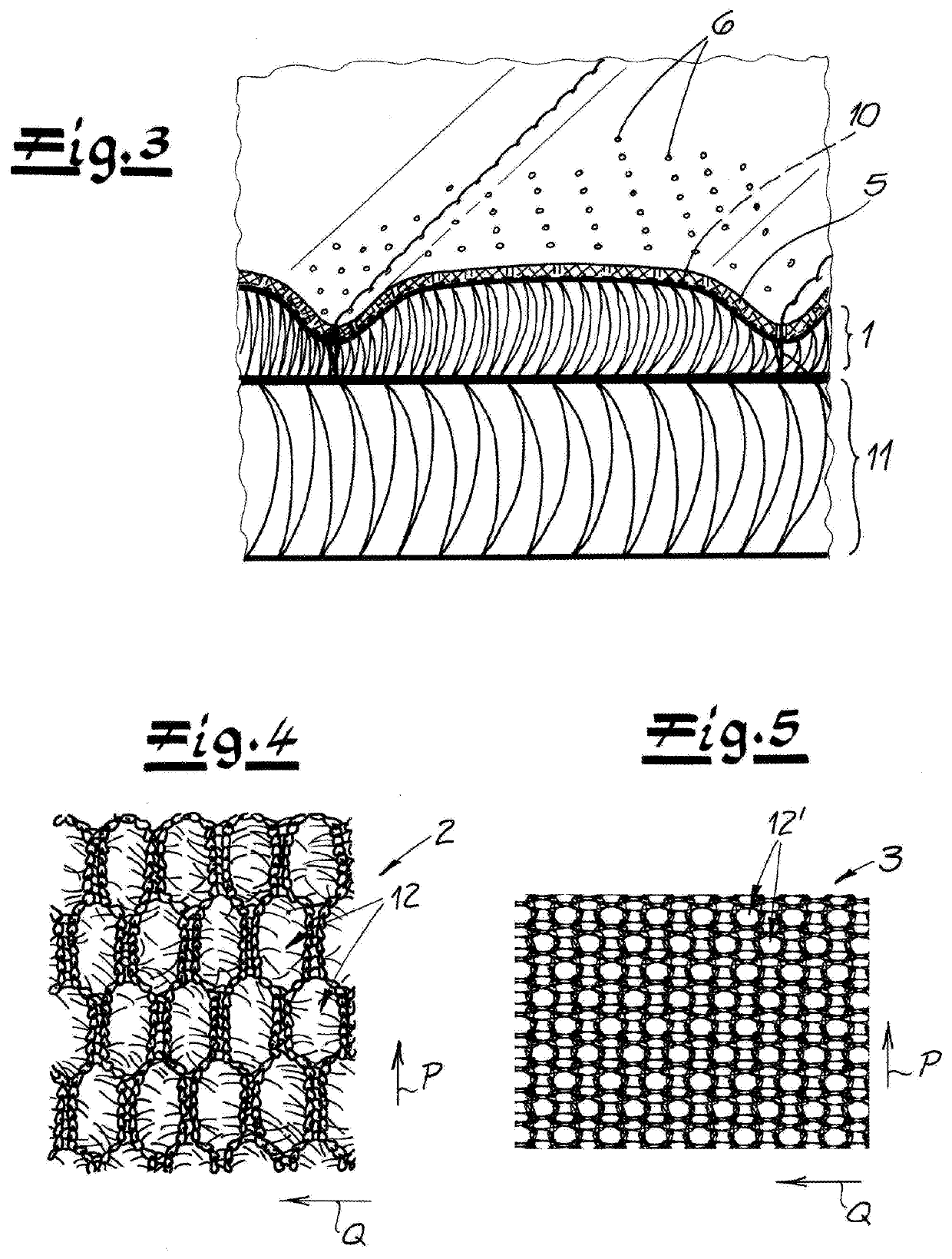
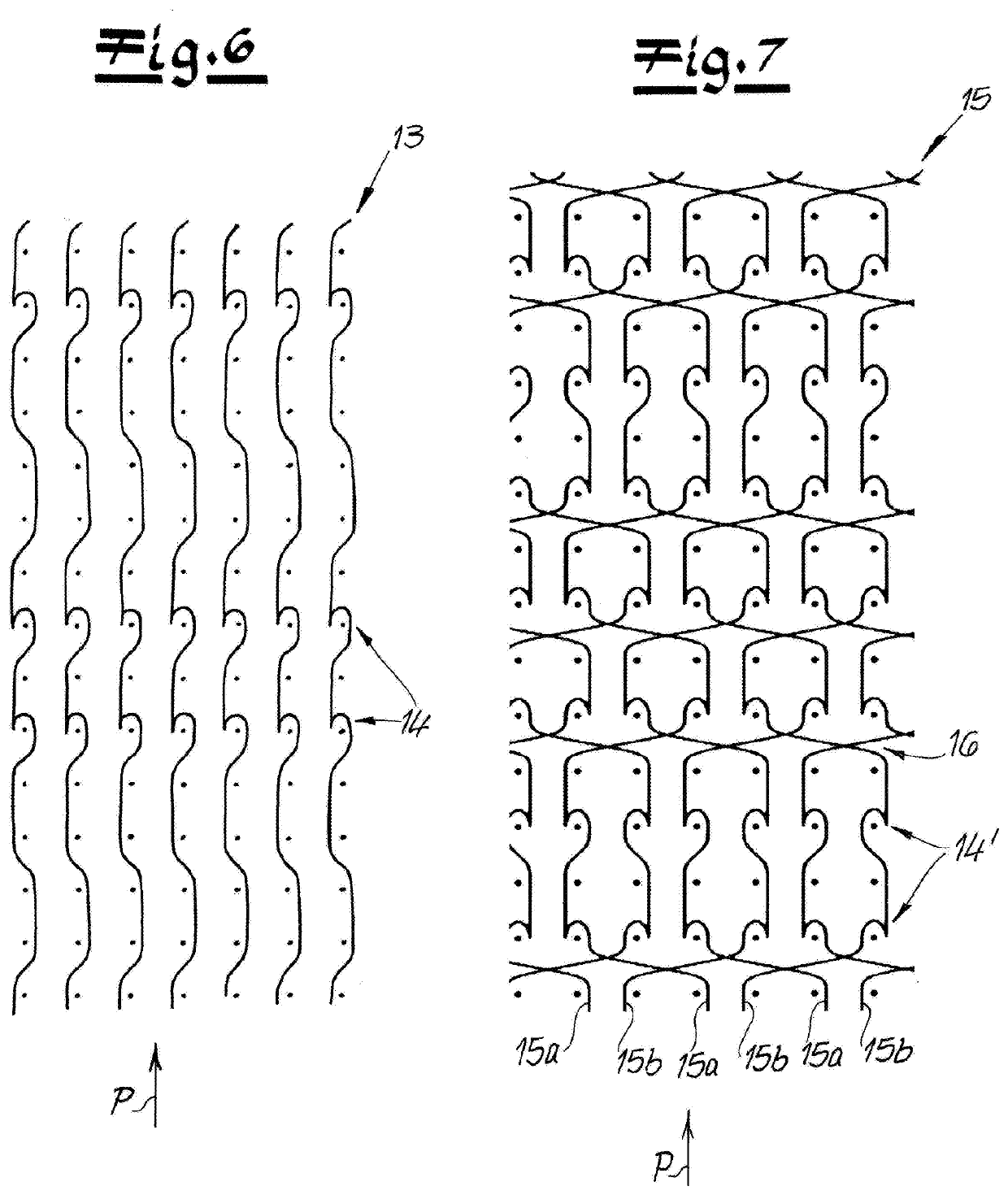
[0077]The spacer fabric 1 has an outer flat warp-knitted fabric layer 2, an inner flat warp-knitted fabric layer 3 and spacer threads 4 interconnecting the warp-knitted fabric layers 2, 3. In the case of the two flat warp-knitted fabric layers 2, 3, stitch wales extends along in the production direction P and stitch courses in the transverse direction Q. In the warp-knitting process, the stitches of a stitch course are formed at the same time with respective guide b...


PUM

PropertyMeasurementUnit
tensionaaaaaaaaaa
thicknessaaaaaaaaaa
thicknessaaaaaaaaaa

Abstract

A warp-knitted textile composite has a spacer fabric that extends in a production direction and a transverse direction and has an outer flat warp-knitted fabric layer of predetermined stretchability, an inner flat warp-knitted fabric layer of lesser stretchability in the production and transverse directions than the outer layer, and spacer threads interconnecting the warp-knitted fabric layers. A decorative cover layer is attached to the outer flat warp-knitted fabric layer and is formed with compressed areas where the spacer fabric is permanently at least partially compressed for structuring the decorative cover layer.

Description

FIELD OF THE INVENTION[0001]The present invention relates to a spacer fabric. More particularly this invention concerns a spacer fabric with several layers.BACKGROUND OF THE INVENTION[0002]A spacer fabric that extends in a production direction and a transverse direction and has an outer flat warp-knitted fabric layer, an inner flat warp-knitted fabric layer, and spacer threads interconnecting the warp-knitted fabric layers, with a decorative cover layer attached to the outer flat warp-knitted fabric layer.[0003]Such a composite is provided in particular for a seat cover or an interior lining or is designed as a seat cover or interior lining.[0004]The assignment of the production direction and transverse direction is customary for warp-knitted textiles, the production direction also being referred to as the warp-knitting direction or the longitudinal direction. In the spacer fabric, the individual yarns forming the knitted fabric run along the production or warp-knitting direction an...

Claims


Application Information

Patent Timeline
Patent Type & Authority Applications(United States)
IPC IPC(8): B32B5/26B32B5/02D04B21/20B32B5/06B32B9/02B32B27/06B32B5/12B32B7/09B32B27/12
CPCB32B2262/0253D10B2331/02B32B5/026B32B2451/00B32B2262/0261D10B2505/08D04B21/20B32B9/025B60N2/58B32B5/12B32B27/12B32B5/26D10B2321/02B32B7/09B32B27/06A47C31/006B32B2262/0276B32B2605/003D10B2331/04B32B5/06D04B21/14B60N2/5891D04B21/16D10B2403/0112D10B2403/0213B32B7/12B32B9/047B32B5/10B32B2479/00B32B2307/724B32B2307/54B32B2250/04B32B2307/732B32B2307/51B32B3/266B32B2250/03D04B21/06
Inventor MUELLER, STEFANJENEWEIN, SABINE
Owner MULLER TEXTIL
Why Eureka
Try Eureka