
Smart charging method

a charging method and smart technology, applied in the direction of safety/protection circuits, emergency protective arrangements for limiting excess voltage/current, transportation and packaging, etc., can solve the problems of inconvenient charging completion insufficient charging completion time of mobile electronic devices, and insufficient battery power of mobile electronic devices. to achieve the effect of shortening the charging period of mobile electronic devices and effective increasing charging efficiency

Active Publication Date: 2020-10-29
CHEN-SOURCE INC
View PDF0 Cites 0 Cited by
  • Summary
  • Abstract
  • Description
  • Claims
  • Application Information

AI Technical Summary

Benefits of technology

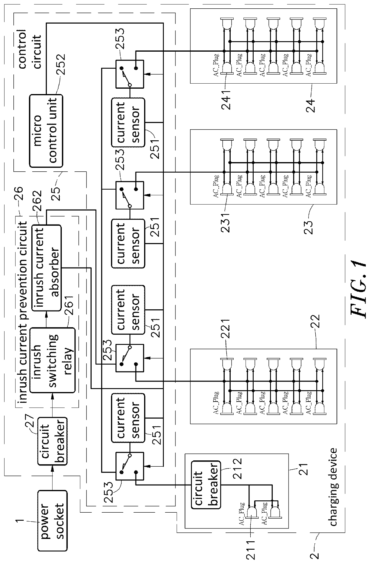
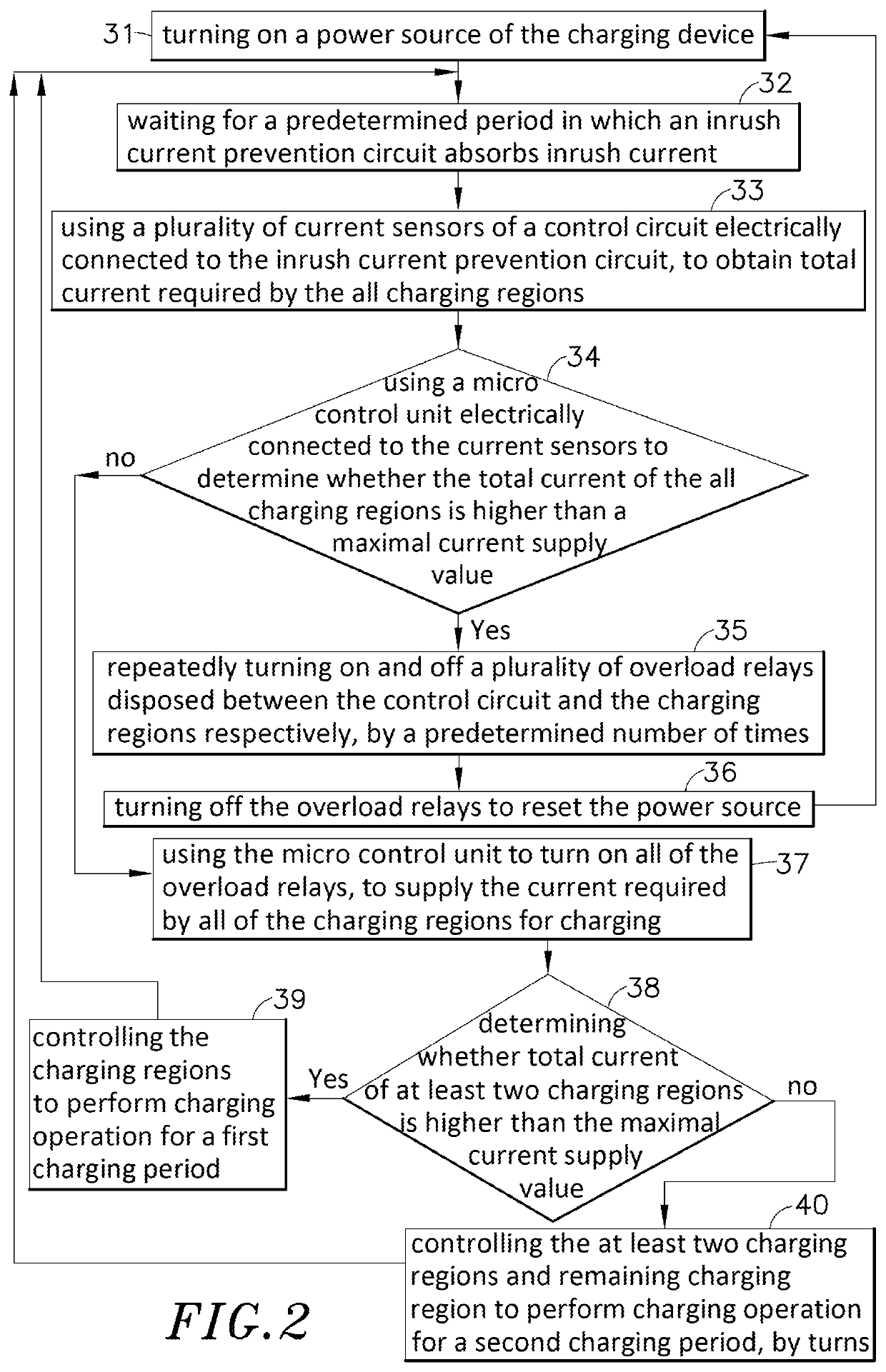
The present invention provides a smart charging method that uses a domestic power source to charge a charging device with power. The charging device has multiple charging regions, each containing multiple sockets to charge different mobile electronic devices. The device has a control circuit to automatically control the charging of the devices. During this process, the method filters out inrush current and uses current sensors to determine the total current required by the charging regions. This information is compared with the maximum current supply value, and if there is a difference, the charging regions are prioritized. If the total current required by all regions is higher than the maximum, one region will charge first for a certain period, and then the other regions will take turn until the devices are fully charged. This method increases charging efficiency and reduces the charging time of the devices.

Problems solved by technology

However, as the processing speed of the electronic product is improved, the mobile electronic device such as smart phone, tablet computer or notebook computer consumes more power.
As a result, when a user operates a mobile electronic product while walking, the battery power of the mobile electronic device is quickly exhausted, and the user needs to find a power socket to charge the battery of the mobile electronic device.
However, when the charging regions are supplied with power by turns, region by region, the charging completion periods of the mobile electronic devices are undesirably delayed.
Therefore, how to develop a fast and efficient smart charging device to solve above problems is a key issue in the industry.

Method used


Image

  • Smart charging method
  • Smart charging method

Examples


Embodiment Construction

[0011]The following embodiments of the present invention are herein described in detail with reference to the accompanying drawings. These drawings show specific examples of the embodiments of the present invention. These embodiments are provided so that this disclosure will be thorough and complete, and will fully convey the scope of the invention to those skilled in the art. It is to be acknowledged that these embodiments are exemplary implementations and are not to be construed as limiting the scope of the present invention in any way. Further modifications to the disclosed embodiments, as well as other embodiments, are also included within the scope of the appended claims. These embodiments are provided so that this disclosure is thorough and complete, and fully conveys the inventive concept to those skilled in the art. Regarding the drawings, the relative proportions and ratios of elements in the drawings may be exaggerated or diminished in size for the sake of clarity and conv...


PUM


Abstract

A smart charging method can supply a charging device with power, and the charging device includes charging regions disposed inside thereof, and each charging region includes sockets for charging mobile electronic devices. The charging device includes a control circuit to perform automatic charging control on the mobile electronic devices plugged into the charging regions. During process of the automatic charging control, inrush current is filtered out, and when the total current required by at least two charging regions is higher than a maximal current supply value, the at least two charging regions take turn to charge for a first charging period; otherwise, the charging regions satisfying the condition, and remaining charging region can take turn to charge for a second charging period until the mobile electronic devices are fully charged. The smart charging method can filter out inrush current and effectively increase the charging efficiency.

Description

BACKGROUND OF THE INVENTION1. Field of the Invention[0001]The present invention provides a smart charging method, more particularly to a smart charging method applied to a charging device to filter out inrush current, so as to effectively increase charging efficiency to shorten charging period of a mobile electronic device.2. Description of the Related Art[0002]In recent years, with rapid development of electronic technology and multimedia information, electronic products such as smart phones, tablet computers, and notebook computers are designed toward light, short, and powerful functions to have features of smaller size, lighter weight, and easy carry, and software and hardware of the electronic products are also continuously innovated, so that the electronic products can be used more flexibly and have improved practical effects, and become indispensable devices widely applied in people's work and life entertainment.[0003]However, as the processing speed of the electronic product ...

Claims


Application Information

Patent Timeline
Patent Type & Authority Applications(United States)
IPC IPC(8): H02J7/00H02H9/02
CPCH02J7/0029H02J7/007H02J7/00304H02H9/02H02J7/00711
Inventor LIN, CHENG-JEN
Owner CHEN-SOURCE INC
Learn More