
Battery power transmission system

A power transmission system and battery charging technology, applied in battery circuit devices, battery data exchange, current collectors, etc., can solve the problems of reducing the service life of the battery 108, increasing the temperature, and high energy consumption of the power conversion circuit 110, so as to reduce charging cycle, reduce energy consumption, and improve the effect of battery power conversion efficiency

Pending Publication Date: 2021-09-17
AOTU ELECTRONICS WUHAN
View PDF0 Cites 0 Cited by
  • Summary
  • Abstract
  • Description
  • Claims
  • Application Information

AI Technical Summary

Problems solved by technology

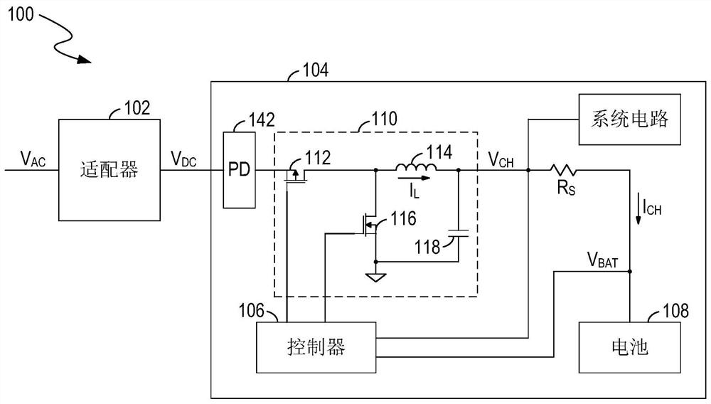
Therefore, the voltage on the power conversion circuit 110 is relatively high, which also makes the power consumption of the power conversion circuit 110 high.
Moreover, the energy consumption of the electric energy conversion circuit 110 will be converted into a large amount of heat, causing the temperature of the electric energy conversion circuit 110 and the battery 108 to increase, which will cause the deterioration of the battery 108 and reduce the service life of the battery 108
Additionally, inductors (or switches) capable of supporting large currents and / or voltages are usually large and expensive
Therefore, the size of the printed circuit board (printed circuit board, printed circuit board) of the power conversion circuit 110 including the inductor 114 and the switches 112 and 116 is relatively large, and the cost is correspondingly high.

Method used


Image

  • Battery power transmission system
  • Battery power transmission system
  • Battery power transmission system

Examples


Embodiment Construction

[0021] Detailed reference will be made below to embodiments of the present invention. Although the present invention is illustrated and described with reference to these embodiments, it should be noted that the present invention is not limited only to these embodiments. On the contrary, the present invention covers all alternatives, modifications and equivalents within the spirit and scope of the invention as defined by the appended claims.

[0022]Certain portions of the following detailed description are presented in terms of symbolic representations of processes, logical blocks, processing procedures, and other operations on data bits in a computer memory. These descriptions and representations are the means by which those skilled in the data processing arts will most effectively convey the substance of their work to others skilled in the art. In this application, a process, logical block, process, or similar thing, is conceived as a structured sequence of steps or instruc...


PUM


Abstract

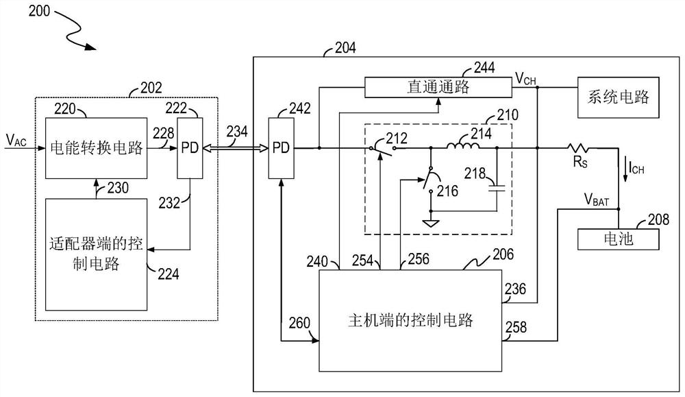
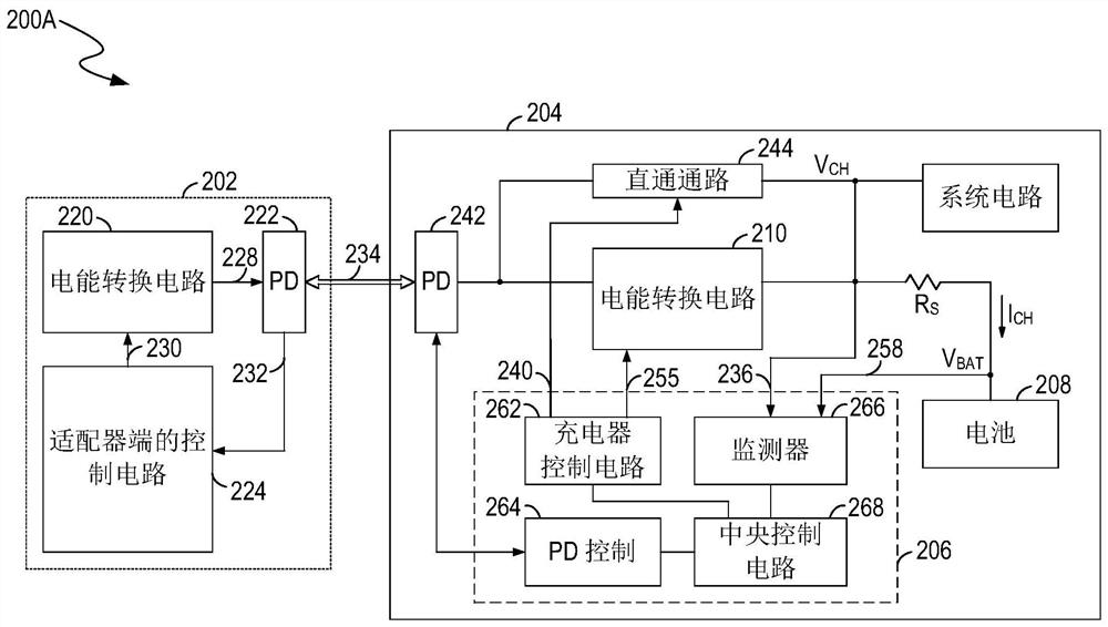
A battery power transmission system includes: a through path that transfers power from a first adapter received from an interface to a battery so as to charge the battery; a conversion circuit, wherein the conversion circuit and the through path are connected to the same interface, the electric energy received by the interface and from the second adapter is converted into output electric energy so as to charge the battery, and the maximum output electric energy of the second adapter is smaller than the maximum output electric energy of the first adapter; and a control circuit connected with the through path and the conversion circuit and used for determining whether the first adapter or the second adapter is connected with the interface. If the second adapter is connected with the interface, the control circuit enables the conversion circuit to generate output electric energy to charge the battery; if the first adapter is connected to the interface, the control circuitry enables the through-path and generates a request and provides the request to the first adapter through the interface, where the request includes information indicative of a target value and instructions requiring the first adapter to provide electrical energy having the target value to the interface.

Description

[0001] This application is a divisional application of an invention patent application with an application date of March 15, 2017, an application number of "201710154735.3", and an invention title of "Power Transmission Controller, Power Transmission System and Power Transmission Method". technical field [0002] The present invention relates to the field of electric energy transmission, in particular to the charging of batteries, including the technology of quick charging and ordinary charging of batteries. Background technique [0003] figure 1 Shown is a block diagram of an existing power transfer system 100 for transferring power to a battery 108 . like figure 1 As shown, power transfer system 100 includes adapter 102 and host device 104 . The host device 104 includes a power-delivery interface 142 (power-delivery interface, PD interface for short), a power conversion circuit 110 (eg, a switching charger), a controller 106 and a system circuit. The power conversion ci...

Claims


Application Information

Patent Timeline
Patent Type & Authority Applications(China)
IPC IPC(8): H02J7/04H02J7/00
CPCH02J7/04H02J7/00714H02J7/007182H02J7/0071H02J7/00034H02J7/0036H02J2207/40H02J7/00H02J7/00036H02J2207/20Y02B40/00
Inventor 栗国星王明峰彭新生
Owner AOTU ELECTRONICS WUHAN
Learn More