

Force-Mitigating Athletic Shoe
- Summary
- Abstract
- Description
- Claims
- Application Information
AI Technical Summary
Benefits of technology
Problems solved by technology
Method used
Image

Examples
first embodiment
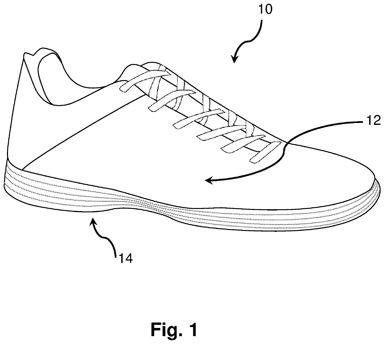
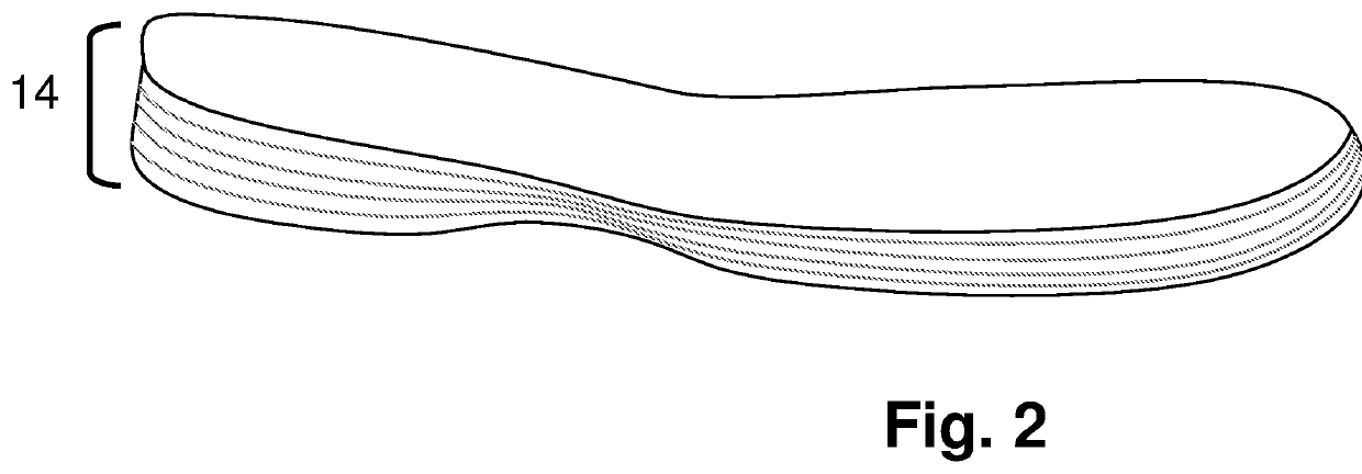
[0056]The athletic shoe 10 according to the invention is shown in FIGS. 1-8. The athletic shoe soles shown in FIGS. 1-8 are designed to protect an athlete's lower extremities against both injurious torsional [i.e., torque] forces and injurious longitudinal forces.
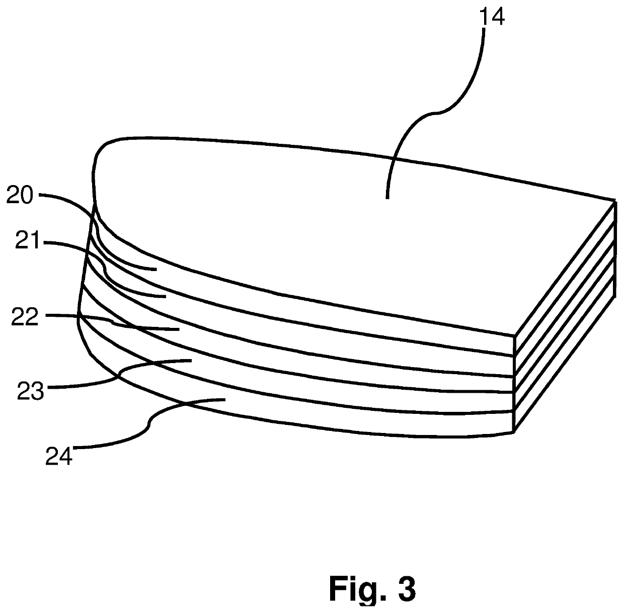
[0057]The shoe sole shown in FIGS. 1-8 comprises an upper body 12 and a multi-layer composite sole 14. Multi-layer composite sole 14 is shown in FIGS. 2-8 as comprising 5 thin layers of materials, although the exact number of layers could be more or less than 5 depending upon the specific situation the shoe is designed for. As shown in FIG. 3, sole 14 comprises layers 20, 21, 22, 23 and 24. Layers 20, and 24 are designed to provide rigid translational [i.e., straight ahead] stability during competition, like a traditional athletic shoe, only up to a pre-determined, athlete-specific, target pre-injury force threshold. These layers will also contribute limited rigidity during lateral as well as rotational [i.e., twisting] for...
second embodiment
[0066]FIGS. 12-14 show a force-mitigating athletic shoe sole constructed according to the invention. The three figures will be described together with it being understood that elements shown in one figure may or may not be shown in the other figures.
[0067]Sole 70 is a multi-layer composite force-mitigating sole similar in construction to the first embodiment soles shown and described above. Multi-layer composite sole 70 is shown as comprising composite layers 73, 74, and 75, although the exact number of layers could be more or less, as desired. Sole 70 comprises materials similar to those of the first embodiment. Multi-layer sole 70 has a cut-out or channel 72 incised into the outer surface of layer 73. Channel 72 is shown in the figures as being incised into the forward portion of sole 70. It should be understood that the exact placement of channel 72 can and will vary depending upon the desired force-resisting characteristics of sole 70 just as the width, depth and exact pathway o...
third embodiment
[0076]FIG. 24 is a plan view of yet another alternate version of a force-mitigating sole constructed utilizing portions of all three embodiments of the invention. It is noted that FIG. 25 is a view taken along the plane I-I of the sole shown in FIG. 24. FIGS. 24 and 25 will be described together. In the invention, the force-mitigating sole is strategically weakened to provide the desired temporary deformation by providing inserts in the sole rather than by providing a channel incised into the sole. However, there is no reason why a force-mitigating sole cannot be constructed using multiple embodiments of the invention in the same force-mitigating sole. Indeed, a force-mitigating sole may be constructed using all of the embodiments of the invention. This is illustrated in FIGS. 24 and 25. Force-mitigating sole 92 comprises three layers 97, 98 and 99. Sole 92 has cut-outs 93, 93′, 94 and 94′ incised into inner layer 98, although the cut-outs could be in layer 99 or layer 97, if desire...
PUM
 Abstract
Description
Claims
Application Information