Small space rough terrain mobility transport

Inactive Publication Date: 2009-04-23
MOORHEAD CRAIG L +1
View PDF8 Cites 3 Cited by
  • Summary
  • Abstract
  • Description
  • Claims
  • Application Information

AI Technical Summary

Benefits of technology

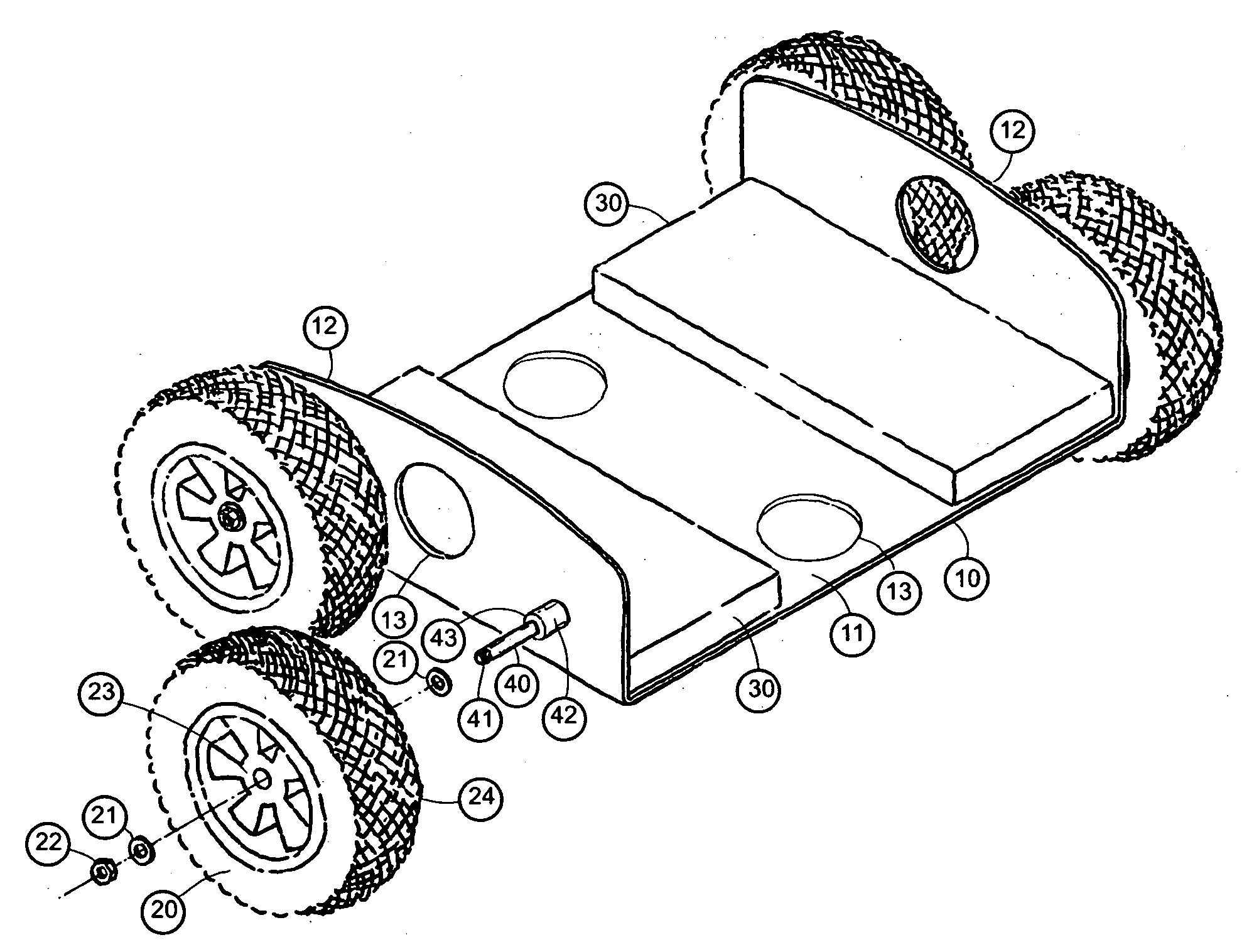
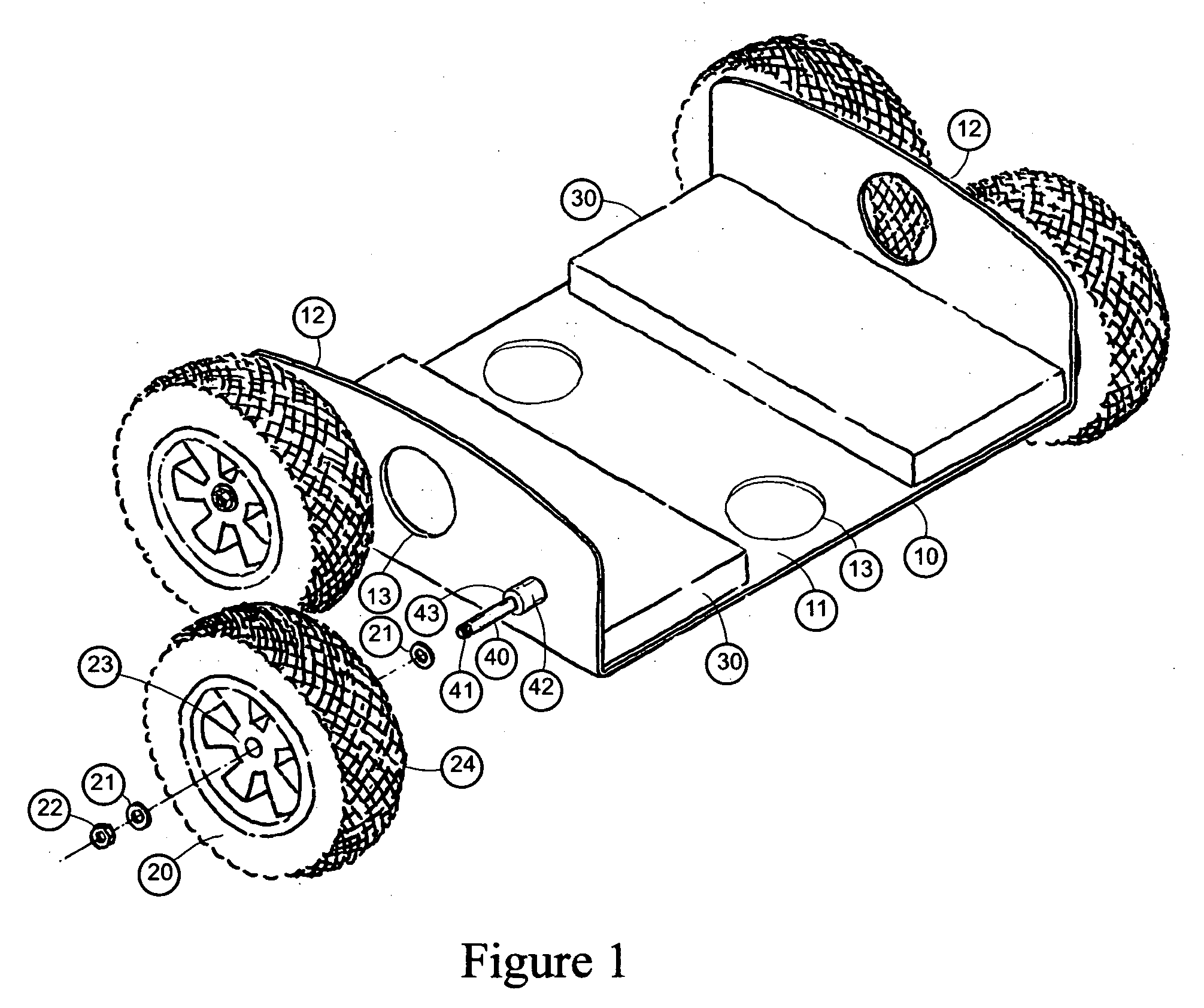
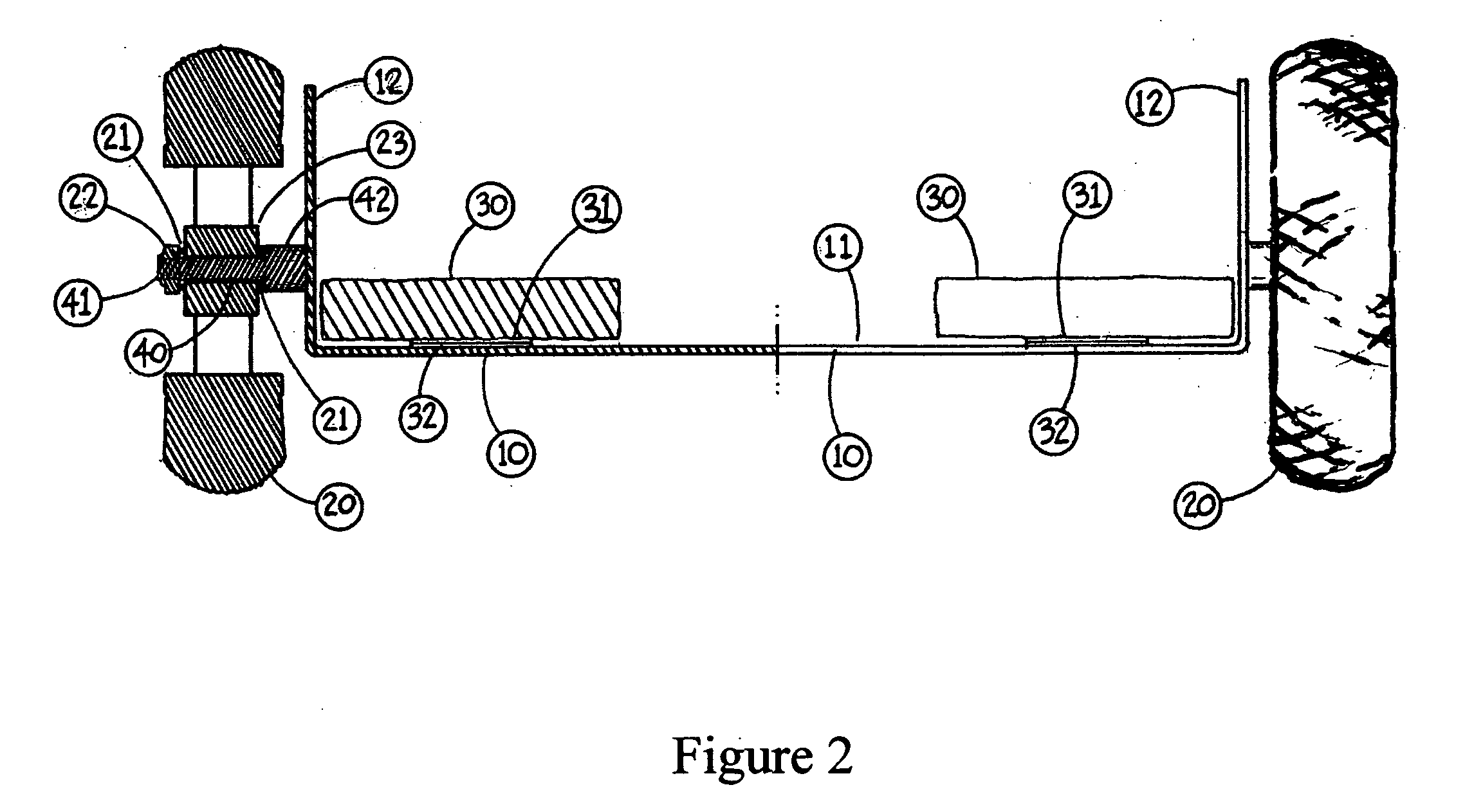
[0014]To attain this, the present invention generally comprises a deck assembly 10, a plurality of axle studs 40, a plurality of wheel assemblies 20 and padding 30. The deck assembly 10 includes turned up edges at each side to create a wheel guard 12 that protects the operator from contact with the wheels 20 and provides the means to control the direction of travel. The wheels 20 are of a size to fit into a low clearance area while maintaining low resistance while rolling across rough and soft surfaces such as soils. The wheel tread 24 is conducive for providing traction across rough terrain and soft soils. The wheel construction is sufficiently flexible to provide shock absorption. A material that is placed on top of the deck surface 11 and is water and tear resistant while being sufficiently soft to provide shock absorbing characteristics while shaped in a profile for the comfort of the operator. The axle stud 40 has an attachment end 42 and an axle end 41. The shape of the axle stud 40 is cylindrical and is preferably larger in diameter at the attachment end 42 than the axle end 41 and creates a shoulder 43 to support one of the two sides of the wheel assembly 20. Further the length of the widened attachment end 42 is a length sufficient to provide adequate clearance between the wheel assembly 20 and the wheel guard 12 that it is attached to. The axle stud 40 is smaller in diameter at the axle end 41 and is continuously straight for a length to be equal to the width of the wheel assembly hub 23 plus the thickness of the attachment washers 21 and threaded nut 22 necessary to secure the wheel assembly 20 to the axle stud 40. Threads are cut into the end most area 41 of the axle stud 40 for a length sufficient to receive the corresponding washers 21 and threaded nut 22 that secures the wheel assembly 20.
[0025]Another objective is to provide a small space rough terrain mobility transport that is light weight and compact in size so as to enter into and be removed from conventional under-floor access scuttle openings.

Problems solved by technology

While the conventional creepers are suited for conditions found in many workshops and on concrete driveways, they are impractical on uneven and soft surfaces commonly found in a crawlspace under a building and under mobile homes, for example.
Particularly, the size of the platform is insufficient for traversing over, under and around obstructions such as rocks, foundation walls, plumbing pipes, and heating ducts commonly found thereon.
Also, the wheels of prior art creepers are ineffective for support on soft and uneven terrain including loose soil and rocks.
Another problem with conventional crawler transports are that they presume that the operating person will be lying on their back and using their legs and feet to facilitate movement which unnecessarily restricts the operating person's visibility while moving in a forward direction.
Another problem with conventional crawler transports are the wheel types do not provide adequate functionality over rough terrain.
Another problem with conventional crawler transporters are they depend on the operating person to be lying on the apparatus, on their back, placed directly on the rough terrain surface and pushing themselves with their legs to cause the apparatus to slide.
The creeper of Simpson has significant disadvantages in that movement requires a user to be lying on their back making visibility in the direction of travel difficult.
The main problem with this is movement would be difficult in low vertical clearance spaces.
Further, the creeper of Simpson has a large physical size and a contoured shape that restricts maneuverability movement through a low clearance small space with obstructions and the contoured shape limits a user to only be lying on it on their back which results in restricted mobility of the device.
Additionally, it's physical size and shape inhibits mounting and dismounting in constricted areas.
The creeper of Black has significant disadvantages in that movement requires the user to be lying on their back making visibility in the direction of travel difficult, and the creeper has limited turning capability, if any, particularly on hard, flat surfaces.
Also, traversing over objects other than moderately uneven terrain would not be possible.
Moreover, the long dimension of the creeper restricts maneuverability and significantly limits turning past or over obstacles.
These creepers are ineffective in that they need excessive ground clearance; they employ narrow wheels which have little float or traction in soft turf; they require padding for operator protection from sharp structural protrusions; they are useful only on hard or smooth surfaces; and / or they are not effective in hard or rocky soil.
While these devices may be suitable for the particular purpose to which they address, they are not suitable for assisting a person in moving through a small low clearance space with rough terrain such as the crawl space beneath a building.
The main problem with conventional crawler transports are their physical size and / or contoured shapes impair movement through a small space and impairs movement of an operating person's arms and legs when used in a manner other than lying on their back which results in restricted mobility of the device.
Additionally, their physical size and / or shape inhibits mounting and dismounting in constricted areas.
Another problem is that they presume that the operating person will be lying on their back and using their legs and feet to facilitate movement which unnecessarily restricts the operating persons visibility while moving in a forward direction.
Also, another problem is the wheel types do not provide adequate functionality over rough terrain.
Another problem with conventional crawler transporters is that they depend on the operating person to be lying on their back on the apparatus placed directly on the rough terrain surface and pushing themselves with their legs to cause the apparatus to slide.

Method used


Image

  • Small space rough terrain mobility transport
  • Small space rough terrain mobility transport
  • Small space rough terrain mobility transport

Examples


Embodiment Construction

[0031]Turning now descriptively to the drawings, in which similar reference characters denote similar elements throughout the several views, the attached figures illustrate a small space rough terrain mobility transport which comprises a deck assembly 10, a plurality of axle studs 40, a plurality of wheel assemblies 20 and padding 30. The deck assembly 10 includes turned up edges at each side to create a wheel guard 12 that protects the operator from contact with the wheels 20 and provides the means to control the direction of travel. The wheels 20 are of a size to fit into a low clearance area while maintaining low resistance while rolling across rough and soft surfaces such as soils. The wheel tread 24 are conducive for providing traction across rough terrain and soft soils. The wheel construction is sufficiently flexible to provide shock absorption. A material that is placed on top of the deck surface 11 and is water and tear resistant while being sufficiently soft to be provide ...


PUM


Abstract

A small space rough terrain mobility transport for assisting a person in moving through a small low clearance space with rough terrain such as the crawl space beneath a building. The inventive device includes a deck assembly 10, a plurality of axle studs 40, a plurality of wheel assemblies 20 and padding 30. The deck assembly 10 includes turned up edges at each side to create a wheel guard 12 that protects the operator from contact with the wheels 20 and provides the means to control the direction of travel. The wheels 20 are of a size to fit into a low clearance area while maintaining low resistance while rolling across rough and soft surfaces such as soils. The wheel tread 24 are conducive for providing traction across rough terrain and soft soils. The wheel construction is sufficiently flexible to provide shock absorption. A material that is placed on top of the deck surface 11 and is water and tear resistant while being sufficiently soft to provide shock absorbing characteristics while shaped in a profile for the comfort of the operator. The axle stud 40 has an attachment end 42 and an axle end 41. The shape of the axle stud 40 is cylindrical and is preferably larger in diameter at the attachment end 42 than the axle end 41 and creates a shoulder 43 to support one of the two sides of the wheel assembly 20. Further the length of the widened attachment end 42 is a length sufficient to provide adequate clearance between the wheel assembly 20 and the wheel guard 12 that it is attached to. The axle stud 40 is smaller in diameter at the axle end 41 and is continuously straight for a length to be equal to the width of the wheel assembly hub 23 plus the thickness of the attachment washers 21 and threaded nut 22 necessary to secure the wheel assembly 20 to the axle stud 40. Threads are cut into the end most area 41 of the axle stud 40 for a length sufficient to receive the corresponding washers 21 and threaded nut 22 that secures the wheel assembly 20.

Description

BACKGROUND OF THE INVENTION[0001]1. Field of the Invention[0002]The present invention relates generally to crawler transports and more specifically it relates to a small space rough terrain mobility transport for assisting a person in moving through a small low clearance space with rough terrain such as the crawl space beneath a building.[0003]2. Description of the Related Art[0004]It can be appreciated that crawler transports have been in use for years. Typically, crawler transports are comprised of mechanic's creepers that provides an elongated platform with castors attached to the underside to allow for a person's mobility into a low clearance space while traversing a smooth surface such as beneath an automobile. Another existing product is a creeper type of device utilizing a track drive with attached spring retractable rails for the purpose of providing mobility for a person while lying on their back in accessing low clearance and rough terrain locations such as under a house. ...

Claims


Application Information

Patent Timeline
IPC IPC(8): B25H5/00
CPCB25H5/00B62B2202/42B62B5/0083
Inventor MOORHEAD, CRAIG L.SERRANO, DUANE R.
Owner MOORHEAD CRAIG L
Why Eureka
Try Eureka