Eureka AIR delivers breakthrough ideas for toughest innovation challenges, trusted by R&D personnel around the world.

Fin Stabilizer

a stabilizer and fin technology, applied in the direction of foil-based vessel movement reduction, waterborne vessel, movement controller, etc., can solve the problems of system overheating, early hydraulic component failure, and difficult installation and maintenance, and achieve the effect of improving torque control, and reducing or zero backlash

Active Publication Date: 2020-11-19
NAIAD MARITIME GRP
View PDF13 Cites 4 Cited by
  • Summary
  • Abstract
  • Description
  • Claims
  • Application Information

AI Technical Summary

Benefits of technology

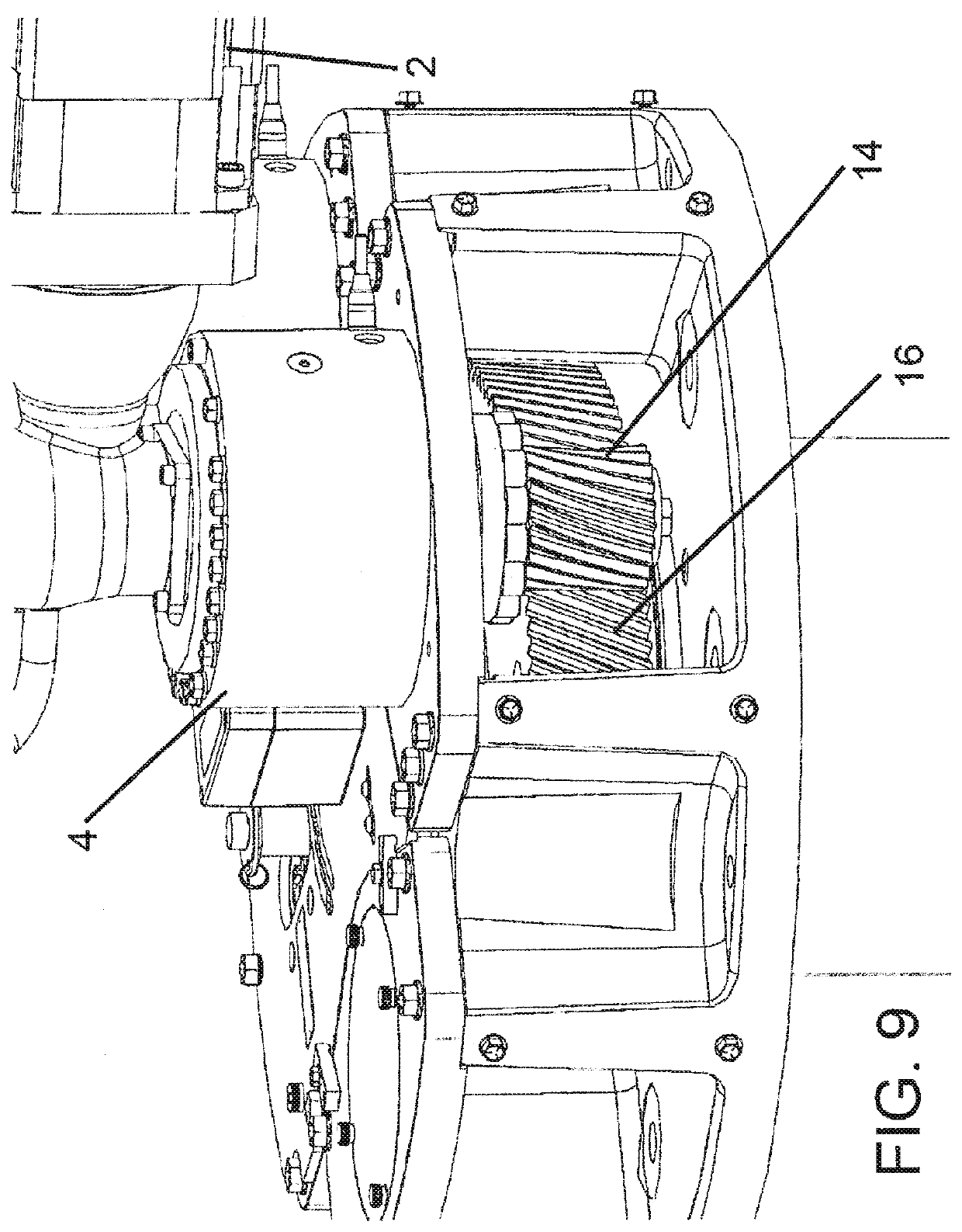
This patent aims to provide a harmonic drive or walking / stepping drive that uses oscillating teeth / gears which progressively step relative to an outer gear. This may be achieved by an individual sliding tooth drive system or other types of eccentrically driven gears that provide significant reduction gearing with reduced or zero backlash. The invention also allows for flexible placement and orientation of motor and drive elements, as well as the use of standardized and interchangeable components to accommodate varied fin and torque requirements. These technical effects may lead to improved torque control, reduced backlash, improved access for repair / adjustment, and compact design for placement in small spaces.

Problems solved by technology

The hydraulic system components all need connection with hose or pipe which can run long distances within a vessel and can be difficult to install and require maintenance.
The hydraulic system also comes with added environmental concerns associated with hydraulic oil because a leak in the system can bleed into the bilge of the vessel and be pumped out with bilge water into the ocean or other body of water where the marine vessel is operating.
In addition, air in the hydraulic system can cause control problems and when the air bubbles collapse they generate intense localized heat in the hydraulic oil leading to system overheating and early hydraulic component failure.
Air in the system can also cause objectionable noise and vibration transmitted throughout the vessel via the interconnecting hydraulic piping.
Routine maintenance or servicing of an otherwise closed hydraulic system, such as changing a hose or a valve, can easily introduce debris or contaminants that can cause intermittent problems that are very difficult to diagnose, require complete system flushing and can lead to expensive repairs.
Another concern of a shipboard hydraulic system is fire.
At higher pressures the hydraulic system is more prone to leaks and when a leak occurs the oil can mist or spray onto hot surfaces in the vessel's machinery spaces or be vaporized, and when exposed to a source of ignition vaporized oil causes fire.
However, planetary gear arrangements are prone to backlash and positioning errors, and those errors increase as the gears experience wear.

Method used


Image

  • Fin Stabilizer
  • Fin Stabilizer
  • Fin Stabilizer

Examples


Embodiment Construction

[0049]Referring now to the drawings, wherein like reference numerals designate corresponding structure throughout the views. The following examples are presented to further illustrate and explain the present invention and should not be taken as limiting in any regard.

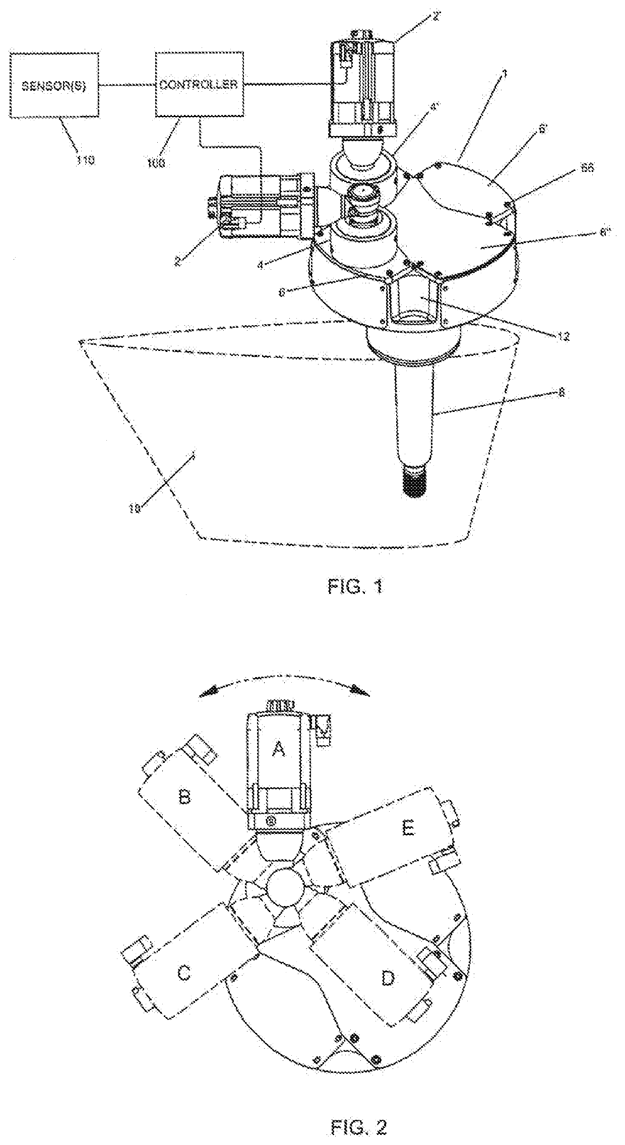
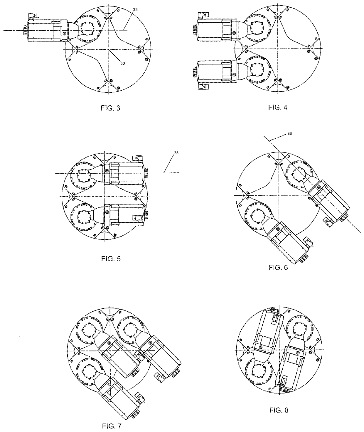
[0050]FIG. 1 shows an example drive unit assembly 1 for a fin stabilizer which employs the oscillating tooth based drive system 4, 4′ to drive the shaft 8 which rotates the fin 18 attached thereto. An example fin that attached to a shaft similar to that shown in FIG. 1 is also shown and described in U.S. Pat Pub No 2016 / 0121978, the content of which is incorporated by reference herein. It is understood that other drive elements made gears and other transmission devices may be employed in connection with this system. As shown, the drive unit assembly 1 is connected to a controller 100 which receives sensor data from sensor(s) 110 to determine what stabilizing commands are necessary based on the conditions and movement of...


PUM


Abstract

A vessel hull stabilization system includes a housing having a rotatable shaft mounted thereto, the shaft configured to connect to a fin such that the fin is located on an outside of the vessel hull and the housing is located on an inside of the vessel hull. A drive system is mounted to the housing and includes a motor and a drive element. The motor is connected to a central shaft of the drive element. The drive element includes a plurality of teeth positioned between the outer element and the central shaft such that when the motor rotates the central shaft, the plurality of teeth oscillate inwards and outwards to interact with teeth in the outer element and thereby cause rotation of a fin shaft connected to the outer element or to the gear having the oscillating teeth. A controller receives sensor readings to determine control signals to send to the motor(s) to impart rotation of the fin.

Description

FIELD OF THE INVENTION[0001]The invention relates to stabilizers and control systems for stabilizers that are used for marine vessels both when making headway and at rest (e.g. at anchor, or zero speed).BACKGROUND OF THE INVENTION[0002]Fin roll stabilizers are commonly mounted to the hull of a vessel below the waterline, usually within the middle one third of the vessel's waterline length and close to the turn of the bilge. These fins typically rotate about an axis that is perpendicular to the lengthwise axis of the vessel. The stabilizer fins are generally aligned parallel to the lengthwise axis of the vessel and rotation of these fins, (optionally combined with flow) creates forces used to reduce the roll of the vessel. The fin roll stabilizers act in some ways that are similar to ailerons on an airplane.[0003]Many traditional fin roll stabilizers for marine vessels are powered hydraulically. In order to create a functioning stabilizing system, a complex setup of hydraulic plumbin...

Claims


Application Information

Patent Timeline
IPC IPC(8): B63B39/06B63J99/00
CPCB63J99/00B63B2039/065B63B39/06B63B79/00
Inventor VENABLES, JOHN D.VENABLES, STEVEN J.COSTEN, CAMERONKNAPP, RYAN W.
Owner NAIAD MARITIME GRP
Why Eureka
Eureka Blog
Learn More