Metal supported solid oxide fuel cell unit and its method of manufacture

Active Publication Date: 2020-11-19
CERES INTPROP CO LTD
View PDF0 Cites 0 Cited by
  • Summary
  • Abstract
  • Description
  • Claims
  • Application Information

AI Technical Summary

Benefits of technology

[0039]The use of the plurality of metal substrate plates allows the metal substrate plates to be combined in a modular manner to obtain a range of fuel cell unit sizes and a range of power outputs as desired, including e.g. a larger fuel cell unit size and therefore larger power output. The attachment of the metal substrate plates to the metal spacer can also reduce the likelihood of bending of the fuel cells within the fuel cell unit, therefore decreasing the risk of reduced electrical conductivity and reduced gas sealing that may occur should

Problems solved by technology

However, increasing the size of fuel cell units (e.g. fuel cell stack layers) can result in mechanical instability.
Movement, particularly flexing, of fuel cell stack units can result in mechanical damage to the fuel cell(s) within them and decreased efficiency/power output and operational lifespan.
This movement/flexing can also reduce the gas seal around the fuel cell unit/fuel cell stack layer, and reduce electrical conductivity, particularly between individual fuel cell unit(s) and the components they form an electrical circuit with.
These problems

Method used


Image

  • Metal supported solid oxide fuel cell unit and its method of manufacture
  • Metal supported solid oxide fuel cell unit and its method of manufacture
  • Metal supported solid oxide fuel cell unit and its method of manufacture

Examples


Example

Embodiment 1

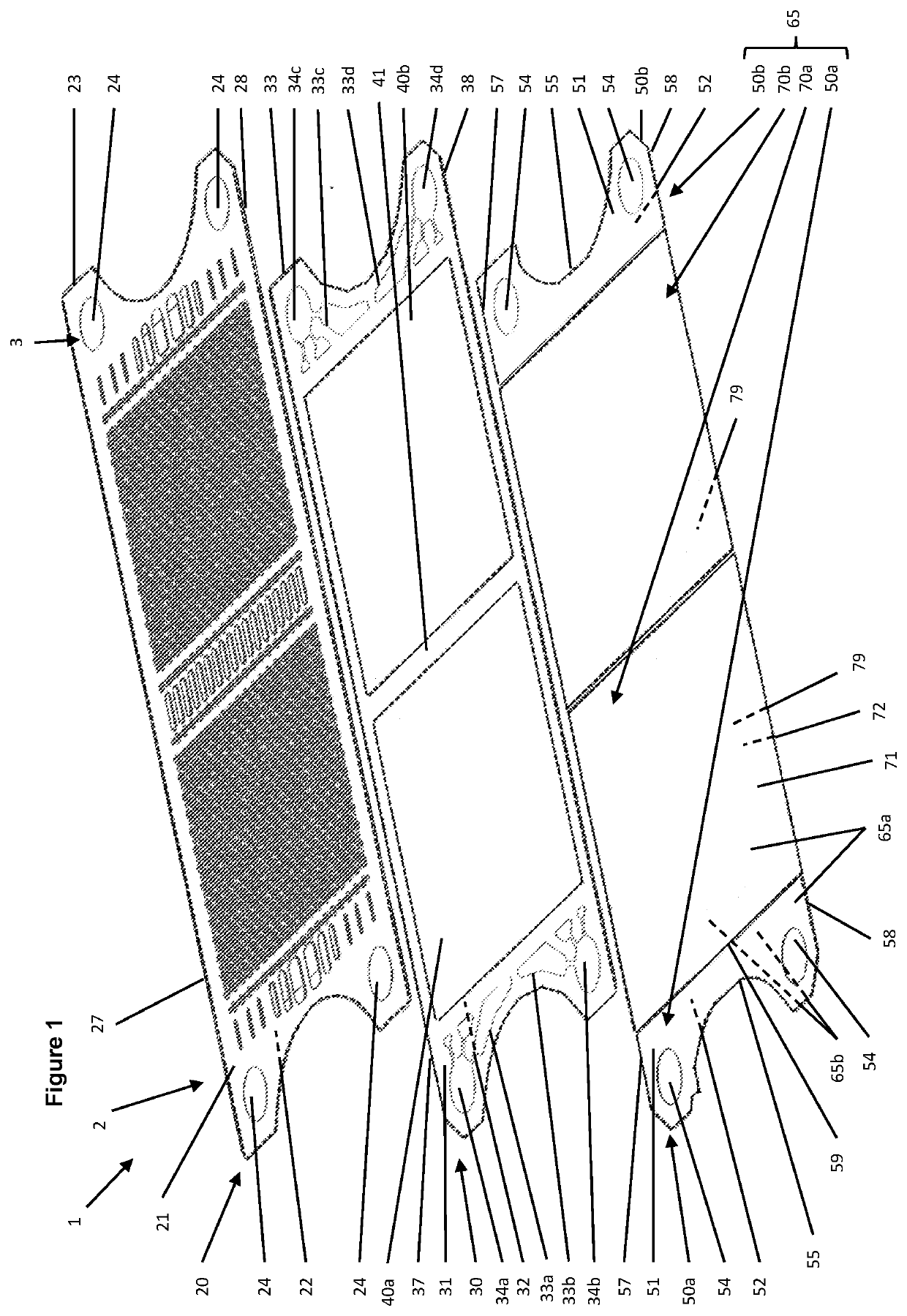
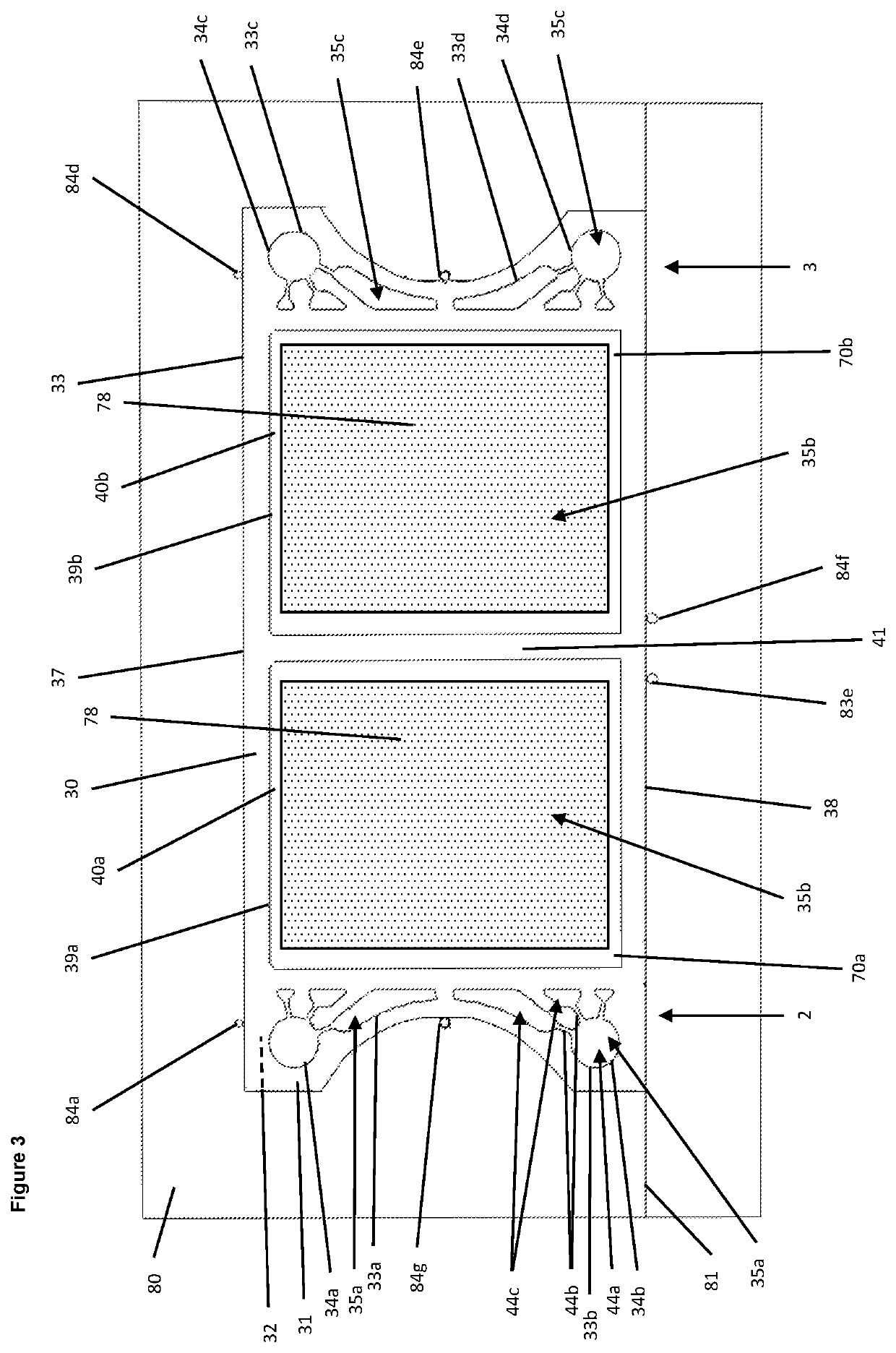
[0076]Fabrication of a metal supported solid oxide fuel cell unit 1 is illustrated in the Figures. Metal supported solid oxide fuel cell unit 1 is for use as a solid oxide fuel cell stack layer.

[0077]In this embodiment, metal supported solid oxide fuel cell unit 1 is fabricated comprising a metal substrate 65 (also referred to as a “substrate layer” or a “metal substrate layer”), a metal spacer 30, and a metal interconnect plate 20.

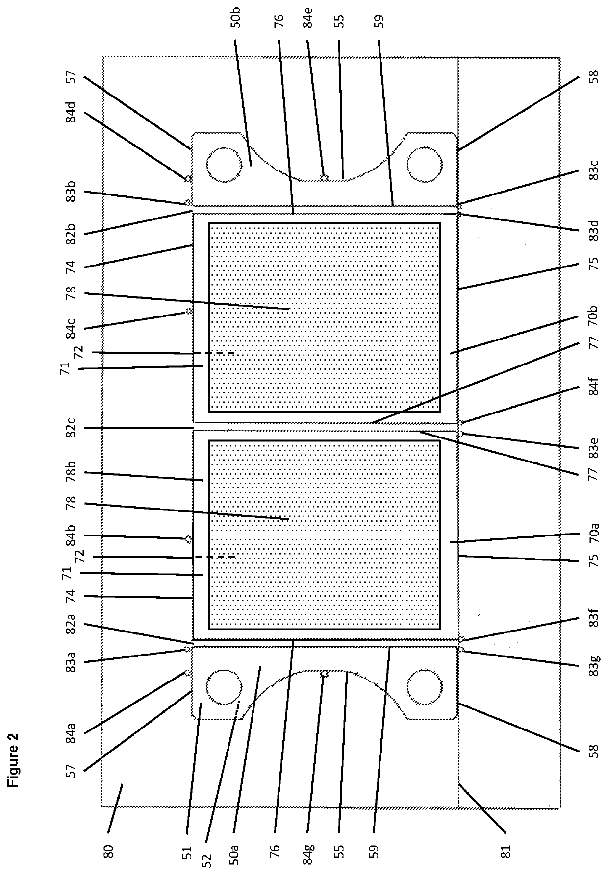
[0078]Metal substrate plates 70a and 70b each comprise a porous region 78 defined by laser-drilled perforations 78a extending between first surface 71 and second surface 72. Fuel cell 79 is deposited over porous region 78 on second surface 72 of metal substrate plates 70a and 70b, and comprises an anode layer deposited over (bonded to) porous region 78 of metal substrate plate 70a, 70b, an electrolyte layer deposited over (bonded to) the anode layer, and a cathode layer deposited over the electrolyte layer. Porous region 78 is surrounded by no...

Example

Embodiment 2

[0137]As shown in FIG. 10, Embodiment 2 is as per Embodiment 1, except that in metal supported solid oxide fuel cell unit 1:[0138](i) blanking plate 50a and metal substrate plate 70a are formed as a combined metal substrate plate 170a, and[0139](ii) blanking plate 50b and metal substrate plate 70b are formed as a combined metal substrate plate 170b.

[0140]Fabrication and operation is otherwise identical to that of Embodiment 1.

Example

Embodiment 3

[0141]As per WO2015 / 136295, a fuel cell stack assembly is formed using a plurality of fuel cell units 1. In more detail, a stack of fuel cell units 1 is assembled on top of a metal base plate (ferritic stainless steel 3CR12), with a Thermiculite 866 gasket electrically insulating the base plate from the adjacent fuel cell unit 1, and a power take off located between the Thermiculite 866 gasket and the adjacent fuel cell unit 1. Thermiculite 866 gaskets are located between the first ends 2 of adjacent fuel cell units 1, and between the second end 3 of adjacent fuel cell units. A power take-off is then positioned upon the top (i.e. the exposed) fuel cell unit 1, a Thermiculite 866 gasket is then placed on top of the power take-off, and a metal end plate (ferritic stainless steel 3CR12) placed upon the Thermiculite gasket. Compressive force is then exerted by compression means between the base plate and the end plate, and a skirt attached to the base plate and the end plate...


PUM


Abstract

The present invention relates to an improved metal supported solid oxide fuel cell unit, fuel cell stacks, fuel cell stack assemblies, and methods of manufacture.

Description

SCOPE OF THE INVENTION[0001]The present invention relates to an improved metal supported solid oxide fuel cell unit, fuel cell stacks, fuel cell stack assemblies, and methods of manufacture.BACKGROUND OF THE INVENTION[0002]Teachings of fuel cells, fuel cell stacks, fuel cell stack assemblies, and heat exchanger systems, arrangements and methods are well known to one of ordinary skill in the art, and in particular include WO02 / 35628, WO03 / 07582, WO2004 / 089848, WO2005 / 078843, WO2006 / 079800,WO2006 / 106334, WO2007 / 085863, WO2007 / 110587, WO2008 / 001119, WO2008 / 003976, WO2008 / 015461, WO2008 / 053213, WO2008 / 104760, WO2008 / 132493, WO2009 / 090419, WO2010 / 020797, WO2010 / 061190, WO2015 / 004419, WO2015 / 136295, WO2016 / 124929, WO2016 / 124928, WO2016 / 128721 and WO2016 / 083780. All publications referenced herein and their references are incorporated herein by reference in their entirety. Definition of terms used herein can be found as necessary in the above publications.[0003]Fuel cell stacks, fuel cell s...

Claims


Application Information

Patent Timeline
IPC IPC(8): H01M8/1286H01M8/1097H01M8/0232H01M8/2404H01M8/2432H01M8/2483
CPCH01M8/0232H01M8/2432H01M8/2404H01M8/2483H01M2008/1293H01M8/1286H01M8/1097H01M8/2425H01M8/006H01M8/0202H01M8/0271H01M8/2418Y02E60/50Y02P70/50H01M8/0258H01M8/1226H01M8/0206
Inventor BALLARD, ANDREWDOMANSKI, TOMASZTUNBRIDGE, JONATHANHARMAN, JONROBERTSON, ALANDUARTE, DIANABRUNTON, ADAM
Owner CERES INTPROP CO LTD
Why Eureka
Try Eureka