Sweeping and fire extinguishing device

a fire extinguishing device and vacuuming technology, applied in the field of smart homes, can solve the problems of large equipment size and occupied space, and achieve the effects of avoiding fire spread, simple structure, and safe and reliable operation

Active Publication Date: 2020-12-10
SHENZHEN QIANHAI RUIFU TECH CO LTD
View PDF0 Cites 8 Cited by
  • Summary
  • Abstract
  • Description
  • Claims
  • Application Information

AI Technical Summary

Benefits of technology

[0017]The present invention has the beneficial effects that the sweeping and fire extinguishing device of the invention comprises a sweeping robot, a fire extinguishing mechanism and a body frame, wherein the fire extinguishing mechanism can move up and down on the body frame. Under normal circumstances, the sweeping robot is separated from the fire extinguishing mechanism and the sweeping robot realizes its functions of floor sweeping and surroundings monitoring. When fire danger occurs, it will quickly reach the position of the fire extinguishing mechanism and take the fire extinguishing mechanism to complete fire extinguishing. Simple in structure, and safe and reliable in operation, the invention is able to detect fire danger timely and make response promptly, thus effectively avoiding the spread of fire. In addition, the product of the invention has various functions, takes up less space and reduces the cost.

Problems solved by technology

The fire extinguishing devices currently used indoors are special equipment of relatively large size, which has only single functions and occupies much space.

Method used


Image

  • Sweeping and fire extinguishing device
  • Sweeping and fire extinguishing device

Examples


Embodiment Construction

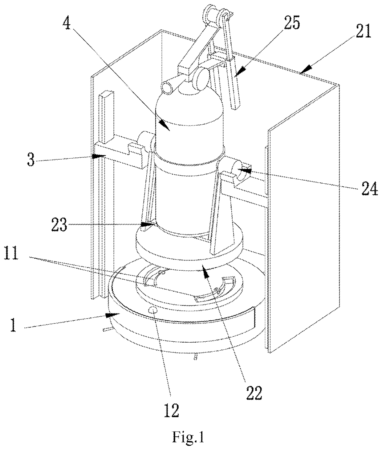
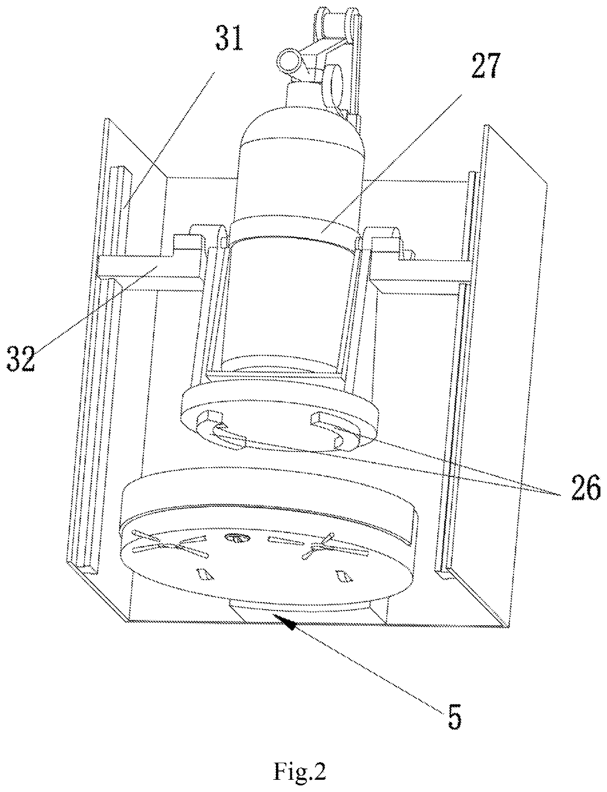
[0021]As shown in FIG. 1 and FIG. 2, the present invention discloses a sweeping and fire extinguishing device, comprising a sweeping robot 1, a fire extinguishing mechanism and a body frame 21. Said sweeping robot 1 comprises a body, a processor, an abutting hole 11 and a camera 12. Said processor is disposed inside the body. Said abutting hole 11 and the camera 12 are both disposed on the body. Said abutting hole 11 is provided with an abutting terminal. Said camera 12 is a 360° rotating camera which is able to monitor the surroundings better. Said camera 12 and the abutting terminal are electrically connected to the processor. The fire extinguishing mechanism comprises a supporting platform 22 and a clamping mechanism 25. The lower end of the supporting platform 22 is provided with an abutting block 26 adapted to said abutting hole 11. Said abutting block 26 is provided with a connecting terminal adapted to said abutting terminal. Said sweeping robot 1 is disposed under said fire ...


PUM


Abstract

The present invention relates generally to the technical field of smart home. More particularly, it relates to a sweeping and fire extinguishing device comprising a sweeping robot, a fire extinguishing mechanism and a body frame, wherein said fire extinguishing mechanism is disposed in a space surrounded by the body frame while said sweeping robot is disposed under the fire extinguishing mechanism. Said sweeping robot comprises a body, a processer, an abutting hole and a camera, wherein an abutting terminal is disposed in said abutting hole. Said camera and the abutting terminal are both electrically connected to the processor; Said fire extinguishing mechanism comprises a supporting platform and a clamping mechanism, wherein said supporting platform comprises an abutting block on its lower end and said abutting block comprises a connecting terminal. Said supporting platform comprises a swinging mechanism for placing a fire extinguisher. Said clamping mechanism is disposed on the control handle of the fire extinguisher. Said clamping mechanism is wirelessly connected with the processor; Said body frame comprises a lifting mechanism which is connected with the swinging mechanism. The invention realizes automatic fire extinguishing by integrating the sweeping robot and the fire extinguishing mechanism into a simple structure, which takes up less space and reduces the cost.

Description

TECHNICAL FIELD[0001]The present invention relates generally to the technical field of smart home. More particularly, it relates to a sweeping and fire extinguishing device.STATE OF THE PRIOR ART[0002]The fire extinguishing devices currently used indoors are special equipment of relatively large size, which has only single functions and occupies much space.SUMMARY OF THE INVENTION[0003]To solve the problems in the prior art, the present invention provides a sweeping and fire extinguishing device that does not occupy much space.[0004]The invention provides a sweeping and fire extinguishing device, comprising:[0005]A sweeping robot, wherein said sweeping robot comprises a body, a processer, an abutting hole and a camera. Said processer is disposed in said body. Said abutting hole and camera are both disposed on the upper end of said body. An abutting terminal is disposed in said abutting hole. Said abutting terminal and the camera are both electrically connected to the processor;[0006...

Claims


Application Information

Patent Timeline
Patent Type & Authority Applications(United States)
IPC IPC(8): A62C13/78A47L11/24A47L11/40A62C27/00B25J11/00
CPCA62C13/78A62C27/00A47L7/00A47L9/2805A47L9/2852A47L9/2873A47L9/2889A47L2201/04A62C37/40
Inventor ZHOU, MAOSONGLIN, SHAOLUN
Owner SHENZHEN QIANHAI RUIFU TECH CO LTD
Why Eureka
Try Eureka