
Heat exchange cell and method

a heat exchange cell and heat exchange technology, applied in water heaters, sustainable buildings, lighting and heating apparatus, etc., can solve the problems of limited use of heat possessed by gases, drawbacks and limitations of the above-mentioned configuration of heat exchange cells, etc., and achieve the effect of maximizing the advantageous technical

Active Publication Date: 2020-12-10
CONDEVO
View PDF3 Cites 3 Cited by
  • Summary
  • Abstract
  • Description
  • Claims
  • Application Information

AI Technical Summary

Benefits of technology

The patent aims to create heat exchange cells that meet the demands of the market while minimizing costs and pressure losses, and maximizing heat exchange efficiency. The invention allows for a balanced and symmetrical distribution of the second heat transfer fluid in the heat exchanger, which results in improved performance.

Problems solved by technology

The Applicant has observed that the aforementioned known configurations of heat exchange cells present some drawbacks and limitations.
In particular, the internal partition element is lapped by the combustion gases only at a radially outer portion thereof having a limited extension before the gases flow away along the axial direction, so that the heat possessed by the gases is not exploited but to a very limited extent.

Method used


Image

  • Heat exchange cell and method
  • Heat exchange cell and method
  • Heat exchange cell and method

Examples


Embodiment Construction

[0233]For the illustration of the drawings, use is made in the following description of identical numerals to indicate construction elements with the same function. Moreover, for clarity of illustration, certain numerical references are not repeated in all the figures.

[0234]With reference to the figures, a heat exchange cell is shown, indicated overall with number 10.

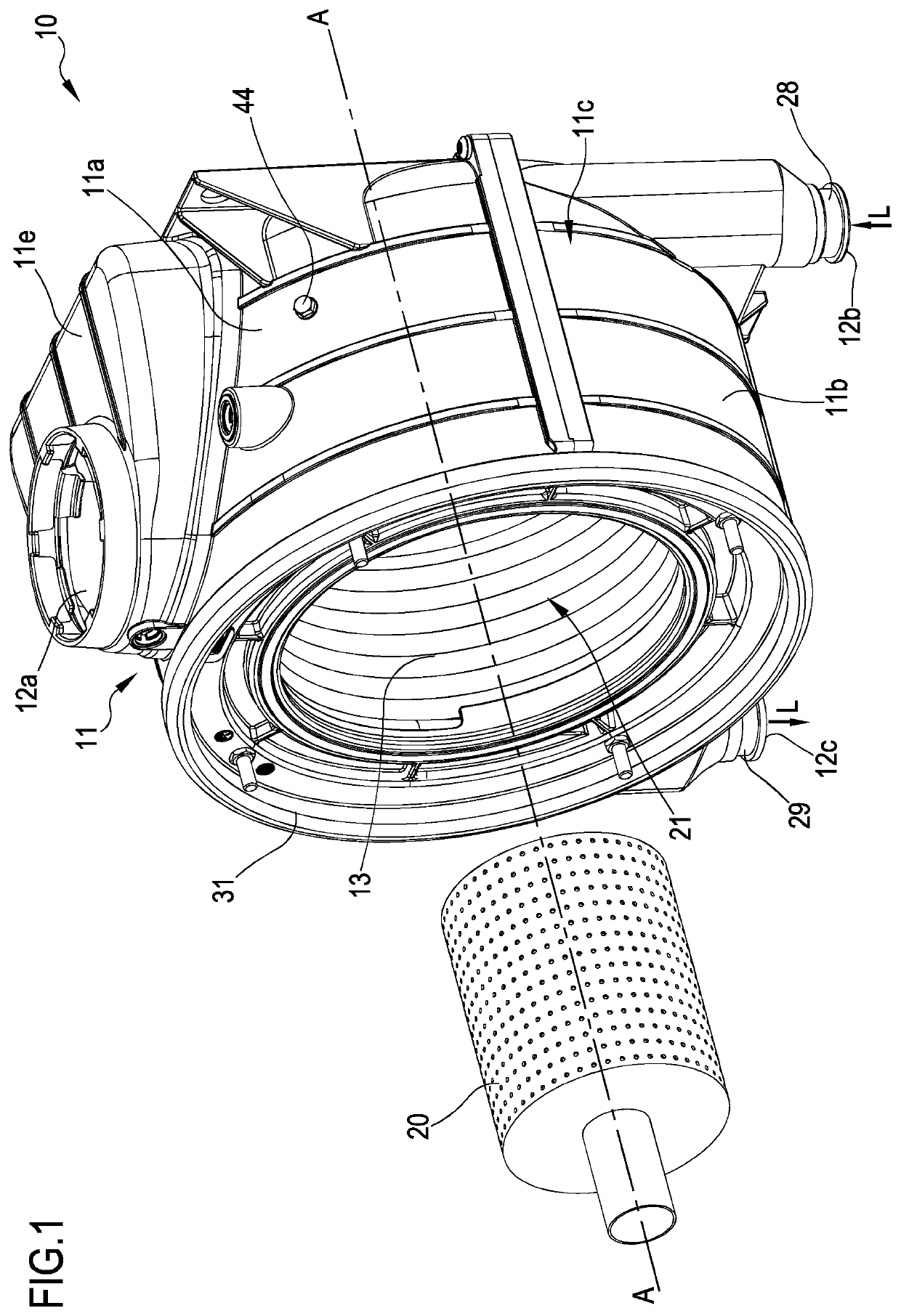
[0235]In the preferred embodiment illustrated in the figures, the heat exchange cell 10 is a gas-liquid heat exchange cell of the so-called condensation type wherein there is an exchange of heat between a first heat transfer fluid, e.g. comprising water to be heated, and a second heat transfer fluid e.g. comprising hot combustion gases coming from a burner shown by number 20 in the appended figures.

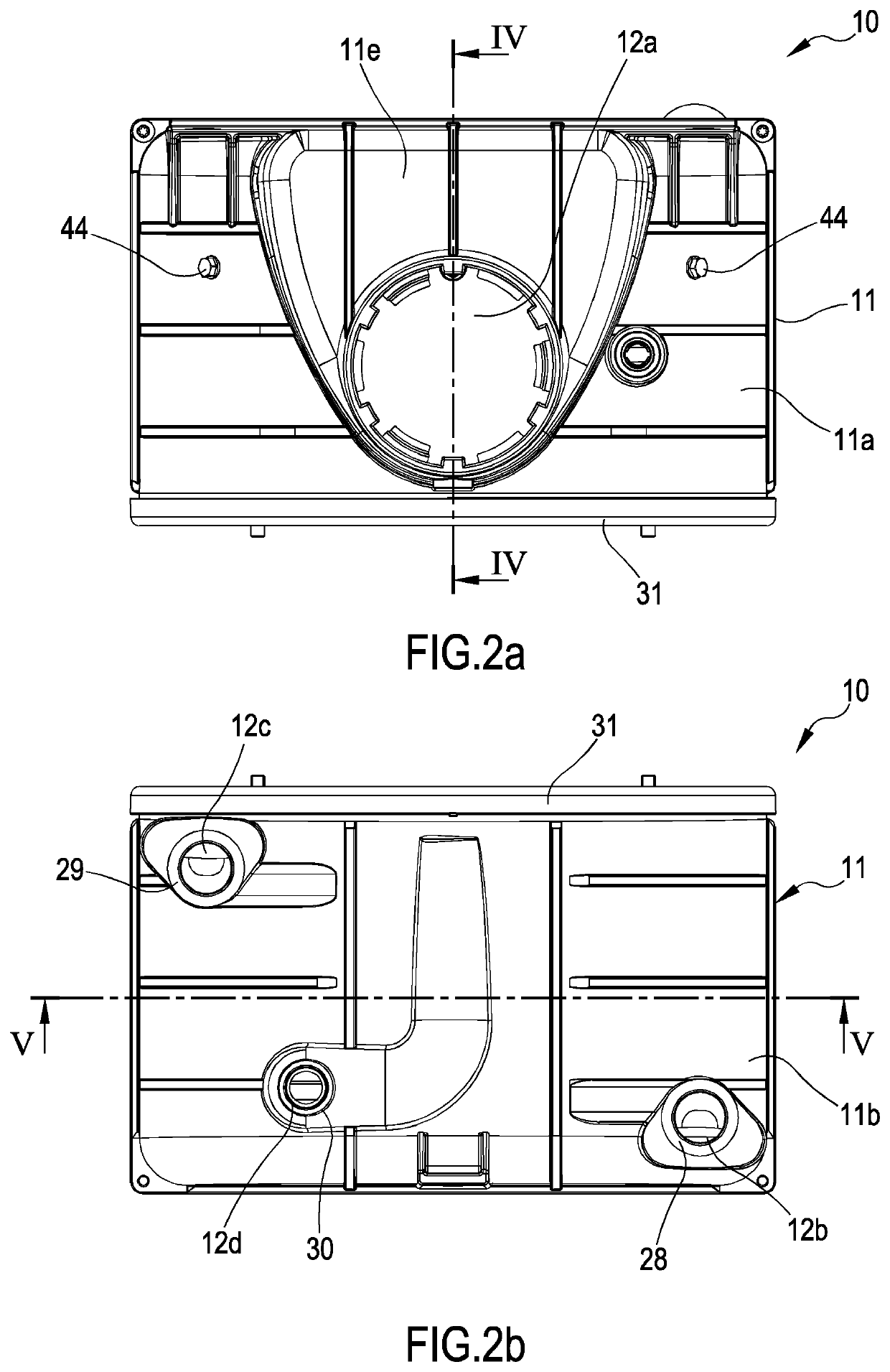
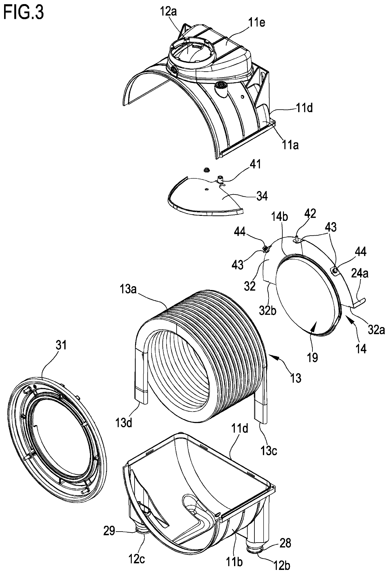
[0236]With particular reference to the preferred embodiment illustrated in the figures, the heat exchange cell 10 comprises a containment casing 11 in which a helically-shaped heat exchanger 13 is mounted.

[0237]Within the sco...


PUM


Abstract

A heat exchange cell (10) is described comprising a helically-shaped heat exchanger (13), mounted in a containment casing (11), in which a first heat transfer fluid circulates; a first heat exchange chamber (22), defined in the casing (11), in which a first heat exchange portion of the heat exchanger (13) is housed and in which a first collection chamber (15) of the second heat transfer fluid is defined externally to the heat exchanger (13); a second heat exchange chamber (26) defined in the casing (11), in which a second heat exchange portion of the heat exchanger (13) is housed and in which—externally to the heat exchanger (13)—a second collection chamber (16) of the second heat transfer fluid is defined; and a fluid outlet passage (35) from the second heat exchange chamber (26) defined in a peripheral side wall (11c) of the containment casing (11) in proximity to a rear wall (11d) thereof. The first and second heat exchange chambers (22; 26) are separated internally to the heat exchanger (13) by a first separating element (14) comprising a substantially plate-shaped body and externally to the heat exchanger (13) by at least a second separating element (32) extending radially between a radially outer wall (13a) of the heat exchanger (13) and the peripheral side wall (11c) of the containment casing (11) so as to define at least one passage (17) of fluid between the first (15) and the second (16) collection chamber of the second heat transfer fluid. The heat exchange cell (10) further comprises a pair of axial separator baffles (24a; 24b), axially extending between the second separating element (32) and the rear wall (11d) of the containment casing (11), and configured to separate a first portion (16a) of the second collection chamber (16) of the second heat transfer fluid defined upstream of the axial separator baffles (24a; 24b) from a second portion (16b) of the second collection chamber (16) of the second heat transfer fluid defined downstream of the baffles (24a; 24b).

Description

BACKGROUND OF THE INVENTION[0001]The present invention relates to a heat exchange cell and a heat exchange method that can be carried out by means of such a cell.[0002]In particular, the invention relates to a heat exchange cell comprising at least one heat exchanger mounted in a respective containment casing, which cell has a preferred although non exclusive use in water heating apparatuses, in heating or air conditioning systems, for both domestic use and for use in complexes of dwelling-houses, industrial areas or shopping areas.[0003]In the following description and in the appended claims, the term: “heat exchange cell” is used to indicate a unit, preferably of a modular type, comprising at least one heat exchanger mounted in a respective containment casing and configured to carry out a heat exchange between a first heat transfer fluid circulating within the heat exchanger, and a second heat transfer fluid flowing in the containment casing externally to the heat exchanger itself...

Claims


Application Information

Patent Timeline
Patent Type & Authority Applications(United States)
IPC IPC(8): F28D7/02F28F9/00
CPCF28F9/001F28D7/024F24H1/43F24H9/0026F28D7/0075F28F2009/226Y02B30/00F24H1/16
Inventor GIANNONI, ROCCO
Owner CONDEVO
Learn More