Ophthalmic optical system, ophthalmic device, and ophthalmic system

a technology of optical system and ophthalmology, applied in the field of ophthalmology optical system, ophthalmology device, ophthalmology system, etc., can solve the problems of complex aberration correction, increase in weight, increase in manufacturing cost,

Pending Publication Date: 2020-12-10
NIKON CORP
View PDF0 Cites 0 Cited by
  • Summary
  • Abstract
  • Description
  • Claims
  • Application Information

AI Technical Summary

Benefits of technology

[0007]An ophthalmic optical system according to a first aspect of the technology disclosed herein includes a reflection unit including a first concave mirror and a second concave mirror: and a lens unit configured to receive light from the reflection unit, wherein: the first concave mirror and the second concave mirror of the reflection unit each include an aperture on an optical axis and have an opposing arrangement to each other in which at least one of a focal point of the first concave mirror or a focal point of the second concave mirror is positioned at the aperture of the other concave mirror, and in which light rays from the focal point of the first concave mirror are reflected by the first concave mirror and the second concave mirror so as to converge as light toward the focal point of the second concave mirror, and the lens unit includes an angle conversion lens that is arranged at a position of the aperture of the first concave mirror which is furthest toward an examined eye side of the lens unit, and that converts an angle of wide-angled converging light from the reflection unit to a smaller angle.

Problems solved by technology

As a result thereof, a wide-angled optical system becomes bulky, leading to an increase in weight and an increase in manufacturing cost.
Moreover, aberration correction is complicated in cases in which large diameter lenses are employed in an attempt to obtain high resolution images with a wide field of view.

Method used


Image

  • Ophthalmic optical system, ophthalmic device, and ophthalmic system
  • Ophthalmic optical system, ophthalmic device, and ophthalmic system
  • Ophthalmic optical system, ophthalmic device, and ophthalmic system

Examples


first exemplary embodiment

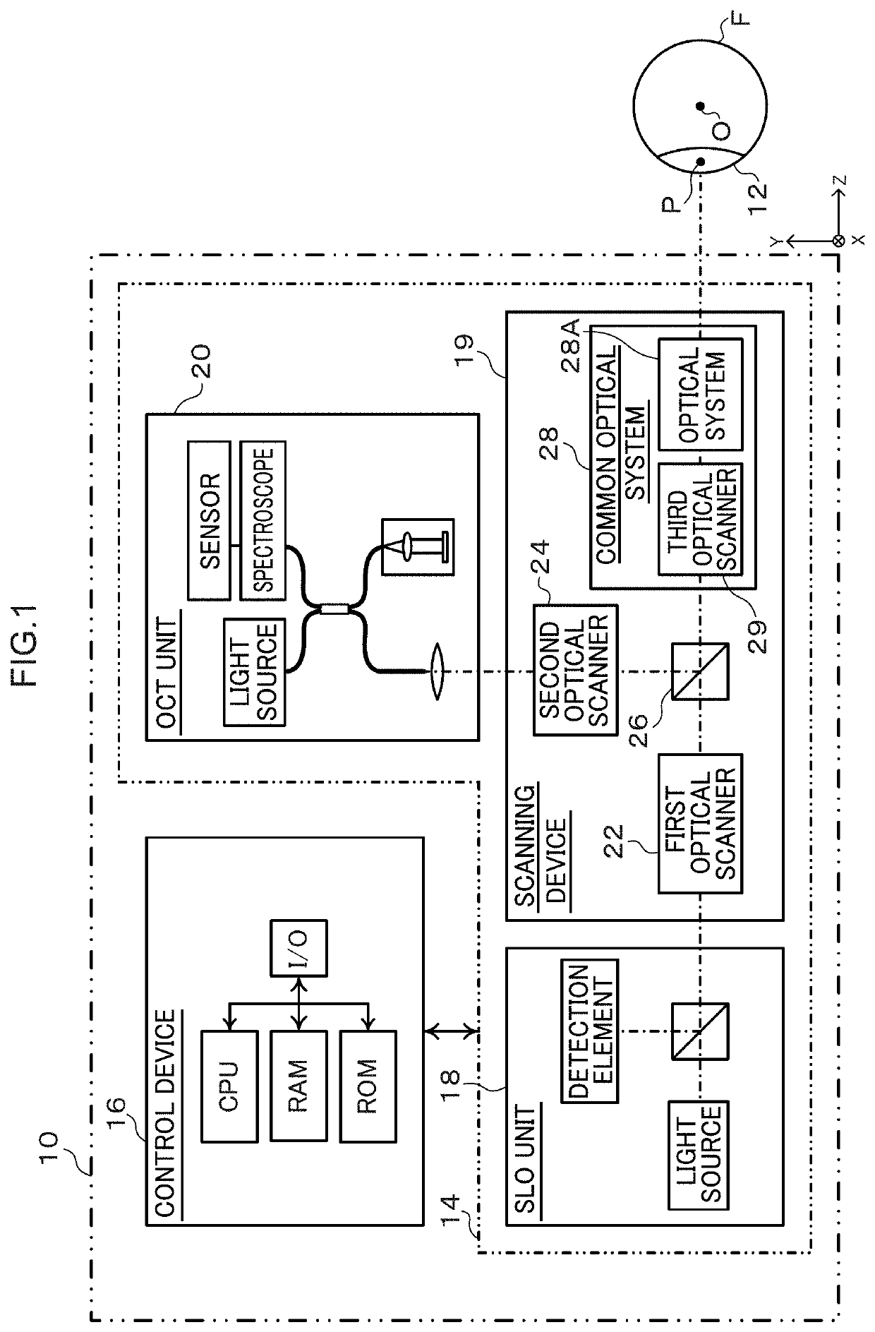
[0030]FIG. 1 is an example of a configuration of an ophthalmic device 10 according to the present exemplary embodiment. The ophthalmic device 10 includes an imaging device 14 for imaging an examined eye 12, and a control device 16 for controlling the imaging device 14. The imaging device 14 includes as imaging functions an SLO unit 18 and an OCT unit 20. The SLO unit 18 functions as a scanning laser ophthalmoscope (hereafter referred to as “SLO”). The OCT unit 20 functions as an optical coherence tomography (OCT) device (hereafter referred to as “OCT”). The control device 16 exchanges information with the imaging device 14 so as to control the operation thereof. The control device 16 generates SLO images based on signals detected by the SLO unit 18. The control device 16 generates OCT images based on signals detected by the OCT unit 20. The control device 16 is, for example, implemented by a computer including a central processing unit (CPU), ROM, and random access memory (RAM), how...

example 1

[0056]Next, description follows regarding the optical system 28A according to an Example 1, with reference to FIG. 7. The same reference numerals are appended to similar configuration to in the first exemplary embodiment, and detailed explanation thereof will be omitted.

[0057]The light rays illustrated in FIG. 7 illustrate a way in which a pupil conjugate point Pcj is formed by the optical system 28A in space at the opposite side to the examined eye 12 side. The optical system 28A includes, in sequence from the examined eye 12 side, the reflection unit 280, the first lens group 281, and the second lens group 282. The reflection unit 280 includes mirror module M01 having a second reflection surface 280Br and a first reflection surface 280Ar arranged in sequence from the pupil Pp side of the examined eye 12. The first lens group 281 includes, in sequence from the pupil Pp side, a positive meniscus lens L01 serving as the angle conversion lens and having a concave surface facing toward...

example 2

[0068]Next, description follows regarding the optical system 28A according to Example 2, with reference to FIG. 9. Example 2 is a modified example of Example 1, the same reference numerals are appended to similar configuration to that of the first exemplary embodiment and Example 1, and detailed explanation thereof will be omitted.

[0069]The rays of light illustrated in FIG. 9 illustrate a way in which a pupil conjugate point Pcj is formed by the optical system 28A in space at the opposite side to the examined eye 12 side. The optical system 28A includes, in sequence from the examined eye 12 side, the reflection unit 280, the first lens group 281, and the second lens group 282. The reflection unit 280 includes mirror module M01 in which a second reflection surface 280B and a first reflection surface 280A are arranged in sequence from the pupil Pp side of the examined eye 12. The first lens group 281 includes, in sequence from the pupil Pp side, a negative meniscus lens L01 having a c...


PUM


Abstract

An optical system is capable observing a peripheral field away from a visual axis and includes a reflection mirror unit forming an image of an examined eye with two concave mirrors in an opposing arrangement facing each other at the examined eye side, this being the upstream side, of a first optical unit and a second optical unit. In the reflection unit there is a conjugate relationship between one focal point thereof and another focal point thereof. By forming an image of the examined eye using the reflection unit a distance can be secured between the examined eye and the optical system and a wide range of the examined eye can be observed.

Description

CROSS-REFERENCE TO RELATED APPLICATIONS[0001]This application is a continuation application of International Application No. PCT / JP2019 / 006608, filed Feb. 21, 2019, the disclosure of which is incorporated herein by reference in its entirety. Further, this application claims priority from Japanese Patent Application No. 2018-031110, filed Feb. 23, 2018, the disclosure of which is incorporated herein by reference in its entirety.TECHNICAL FIELD[0002]Technology disclosed herein relates to an ophthalmic optical system, an ophthalmic device, and an ophthalmic system.BACKGROUND ART[0003]Ophthalmic devices are implemented for performing ophthalmic diagnosis, ophthalmic surgical treatment, and the like. A recent desire is for an ophthalmic device capable of observing the fundus of an eye of a subject (hereafter referred to as examined eye) over a wide range. A wide-angled optical system is utilized to obtain fundus images with a wide field of view. When a wide-angled optical system is confi...

Claims


Application Information

Patent Timeline
Patent Type & Authority Applications(United States)
IPC IPC(8): G02C7/02G02B17/00
CPCG02B5/08G02C7/022G02B17/006A61B3/10G02B17/0856G02B17/0808A61B3/102A61B3/12
Inventor MIZUTA, MASAHIRO
Owner NIKON CORP
Why Eureka
Try Eureka