
Emission control driver stage and display device including the same

Active Publication Date: 2020-12-17
SAMSUNG DISPLAY CO LTD
View PDF0 Cites 4 Cited by
  • Summary
  • Abstract
  • Description
  • Claims
  • Application Information

AI Technical Summary

Benefits of technology

The invention provides emission control driver stages that prevent changes in the electrical properties of transistors and ensure stable supply of the emission control signal to the display device, even at an initial stage of driving. This improves the output quality of the emission control driver and reduces or eliminates unintended flashing caused by the emission of pixels.

Problems solved by technology

Applicant discovered that internal voltages (e.g., node voltages) in the stages of emission control drivers in display devices may be unstable at a beginning of the driving of the display device, which may make it difficult to control the emission of pixels as desired.

Method used


Image

  • Emission control driver stage and display device including the same
  • Emission control driver stage and display device including the same
  • Emission control driver stage and display device including the same

Examples


Embodiment Construction

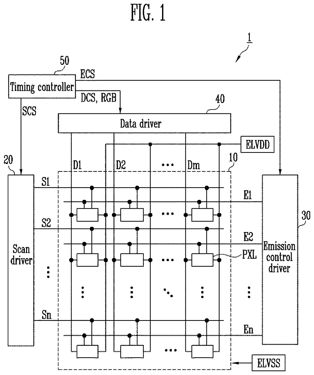
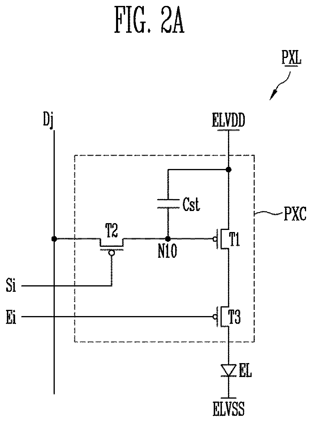
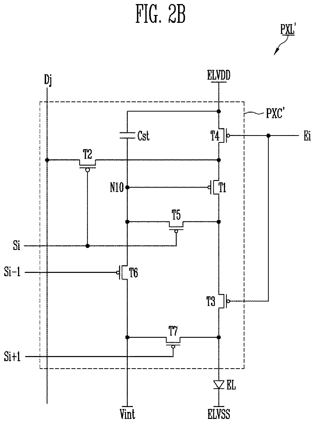
[0041]In the following description, for the purposes of explanation, numerous specific details are set forth in order to provide a thorough understanding of various exemplary embodiments or implementations of the invention. As used herein “embodiments” and “implementations” are interchangeable words that are non-limiting examples of devices or methods employing one or more of the inventive concepts disclosed herein. It is apparent, however, that various exemplary embodiments may be practiced without these specific details or with one or more equivalent arrangements. In other instances, well-known structures and devices are shown in block diagram form in order to avoid unnecessarily obscuring various exemplary embodiments. Further, various exemplary embodiments may be different, but do not have to be exclusive. For example, specific shapes, configurations, and characteristics of an exemplary embodiment may be used or implemented in another exemplary embodiment without departing from ...


PUM


Abstract

A stage in an emission control driver of a display device includes an input unit to control a voltage of a first node and a second node in response to a first input signal supplied from a first input terminal and a second input signal supplied from a second input terminal, respectively; a first controller to control a voltage of a third node and a fourth node in response to a third input signal supplied from a third input terminal and the voltage of the second node; a second controller to control the voltage of the fourth node in response to the voltage of the first node; and an output unit to supply a voltage of a first power supply or a second power supply to an output terminal in response to the voltage of the third node or the voltage of the fourth node. The first controller includes a first transistor and a second transistor connected between the first power supply and the third node; and a third transistor connected between the first node and the third node, the first transistor being turned on in response to the voltage of the second power supply.

Description

CROSS-REFERENCE TO RELATED APPLICATION[0001]This application claims priority from and the benefit of Korean Patent Application No. 10-2019-0068932 filed on Jun. 11, 2019, which is hereby incorporated by reference for all purposes as if fully set forth herein.BACKGROUNDField[0002]Exemplary implementations of the invention relate generally to an emission control driver for a display device and, and more particularly to an emission control driver having stages to supply emission control signals to pixels and a display device including the same.Discussion of the Background[0003]A display device displays an image using pixels disposed in a display unit. The pixels are connected to scan lines and data lines, and are driven by scan signals and data signals supplied through the scan lines and data lines.[0004]The pixels may be further connected to emission control lines, and an emission period of the pixels may be controlled using emission control signals supplied to the emission control li...

Claims


Application Information

Patent Timeline
IPC IPC(8): G09G3/32
CPCG09G3/32G09G2310/0202G09G2310/0278G09G3/3258G09G3/3266G09G2310/0262G09G2300/0426G09G2330/028G09G2310/0286G11C19/28G09G3/2092G09G2310/06G09G2300/0439G09G2310/08
Inventor NA, JI SUKIM, YANG WANMOON, JOONG SOOCHO, YOUNG JIN
Owner SAMSUNG DISPLAY CO LTD
Learn More