Polyaxial strut for external fixation
- Summary
- Abstract
- Description
- Claims
- Application Information
AI Technical Summary
Benefits of technology
Problems solved by technology
Method used
Image

Examples
second embodiment
[0049]FIGS. 10A-10E illustrate the polyaxial strut 1000. The polyaxial strut 1000 includes a proximal head portion 1001 and a distal ball joint 1002. The distal ball joint 1002 may include a ball joint body 1010 and a ball joint stud member 1020 rotatably coupled to the ball joint body 1010. The ball joint stud member 1020 includes a ball member 1021 and a shaft portion 1024. As shown in FIGS. 10A and 10B, the ball joint body 1010 includes a plurality of grooves 1013 configured to accommodate the proximal end of the shaft portion 1024 of the ball joint stud member 1020. The grooves 1013 allow for acute angulation of the ball joint stud member 120 within the ball joint body 1010 at specific angular positions as set by the surgeon. The distal ball joint 1002 additionally includes a ring contact portion 1030 that is attached to the ball joint stud member 1020 using a pin 1022 configured to inhibit rotation of the ball joint stud member 1020 within the ring contact portion 1030.
[0050]Th...
third embodiment
[0052]FIGS. 11A-11D illustrate the polyaxial strut 1100. The polyaxial strut 1100 includes a proximal head portion 1101 and a distal ball joint 1102. The distal ball joint 1102 may include a ball joint body 1110 and a ball joint stud member 1120 rotatably coupled to the ball joint body 1110. The ball joint stud member 1120 includes a ball member 1121 and a shaft portion 1124. The distal ball joint 1102 additionally includes a ring contact portion 1130 that is attached to the ball joint stud member 1120 using a pin 1122 (shown in FIG. 11D) configured to inhibit rotation of the ball joint stud member 1120 within the ring contact portion 1130.
[0053]The polyaxial strut 1100 further includes a strut member 1140 including a U-shaped opening 1147 having an unthreaded opening 1146 on first prong 1140a of the U-shape and a threaded opening 1148 on a second prong 1140b of the U-shape. The unthreaded opening 1146 and the threaded opening 1148 are configured to accommodate a bolt 1150, which se...
fourth embodiment
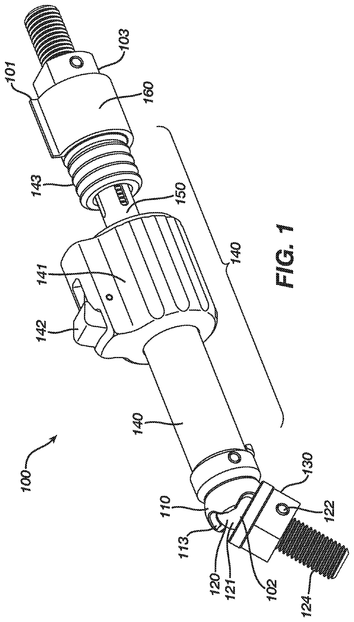
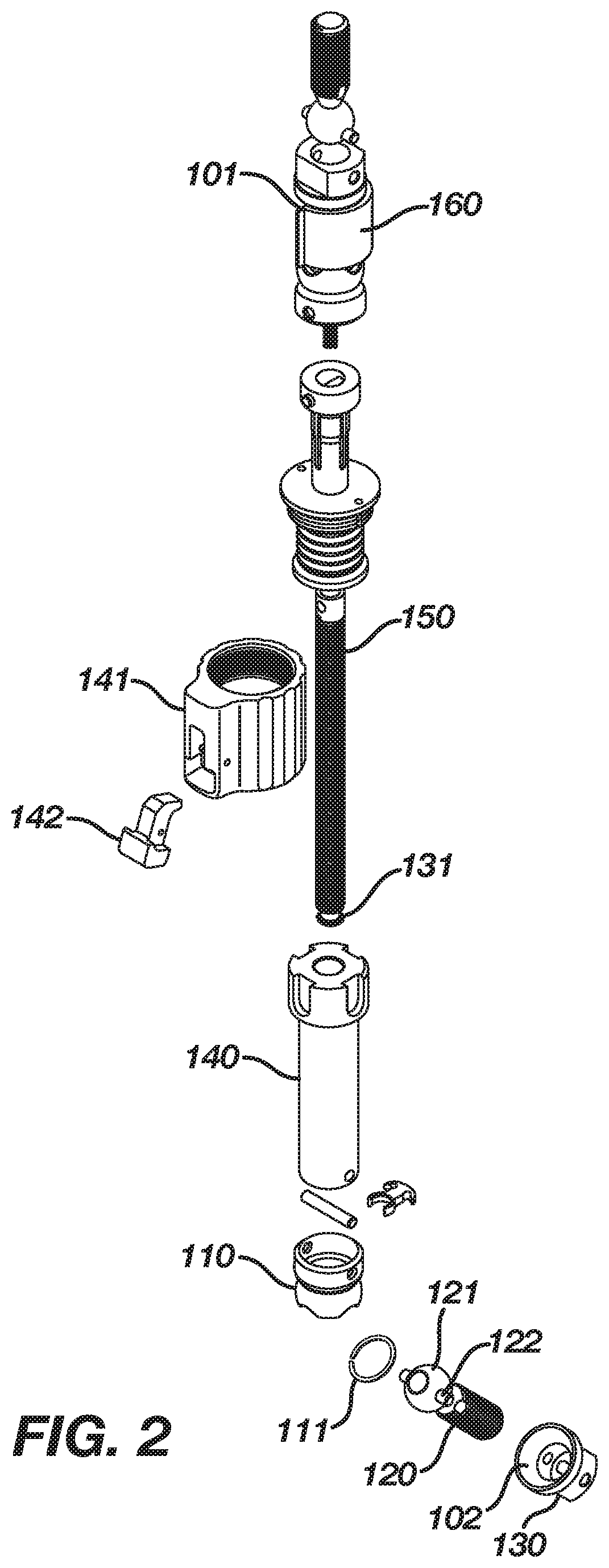
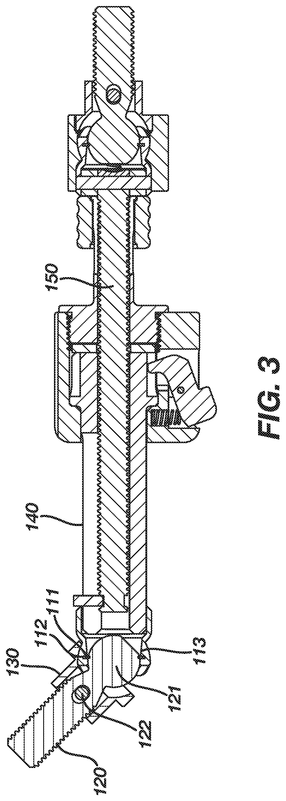
[0054]FIGS. 12A and 12B illustrate the polyaxial strut 100. In this embodiment, the distal ball joint 102 may be further fixed with a removably attached fixator clip 160 that is configured to permanently or temporarily maintain the ball joint body 110, ball joint stud member 120 and ring contact portion 130 in axial alignment during construction of an external fixation device. As shown in FIGS. 12C and 12D, the fixator clip 160 may be substantially C-shaped with outwardly protruding portions 161a, 161b at a first and second tip 162a, 162b of the C shape. In various embodiments, the inner surface 163 of the fixator clip 160 may include ridged portions 164 and concave portions 165 configured to fit snugly over the ball joint body 110 and the ring contact portion 130 in order to permanently or temporarily fix the ball joint body 110, ball joint stud member 120 and ring contact portion 130 in a linear configuration. In use, the fixator clip 160 may be removed at the discretion of the su...
PUM
 Abstract
Description
Claims
Application Information
 - R&D
- Intellectual Property
- Life Sciences
- Materials
- Tech Scout
- Unparalleled Data Quality
- Higher Quality Content
- 60% Fewer Hallucinations
Browse by: Latest US Patents, China's latest patents, Technical Efficacy Thesaurus, Application Domain, Technology Topic, Popular Technical Reports.
© 2025 PatSnap. All rights reserved.Legal|Privacy policy|Modern Slavery Act Transparency Statement|Sitemap|About US| Contact US: help@patsnap.com