Mobile terminal having antenna

a mobile terminal and antenna technology, applied in the direction of polarised antenna unit combinations, individually energised antenna arrays, resonant antennas, etc., can solve the problems of deterioration of radiation efficiency and bandwidth characteristics in each frequency band, two frequency bands too wide for broadband design, and the mounting space of pcb is too small, so as to achieve the effect of improving isolation

Inactive Publication Date: 2020-12-24
LG ELECTRONICS INC
View PDF0 Cites 8 Cited by
  • Summary
  • Abstract
  • Description
  • Claims
  • Application Information

AI Technical Summary

Benefits of technology

[0012]An aspect of the present disclosure is to solve the above-mentioned problems and other problems. Another aspect of the present disclosure is to provide a mobile terminal capable of improving isolation between antennas operating in different frequency bands.

Problems solved by technology

However, when an antenna operating in the first frequency band and an antenna operating in the second frequency band are arranged in separate areas of the mobile terminal, there is a problem in the PCB mounting space.
On the other hand, when a single antenna operates in both the first frequency band and the second frequency band, there is a problem that the two frequency bands are too wide for broadband design.
Moreover, when a single antenna operates in a wide band, there is a problem that radiation efficiency and bandwidth characteristics in each frequency band may be deteriorated.
However, in such an array antenna structure, there is a problem in that poor isolation between different antennas occurs.

Method used


Image

  • Mobile terminal having antenna
  • Mobile terminal having antenna
  • Mobile terminal having antenna

Examples


Embodiment Construction

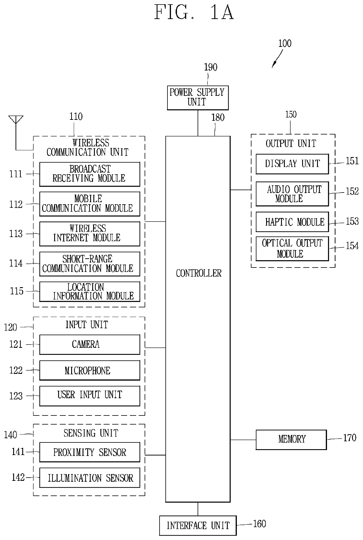
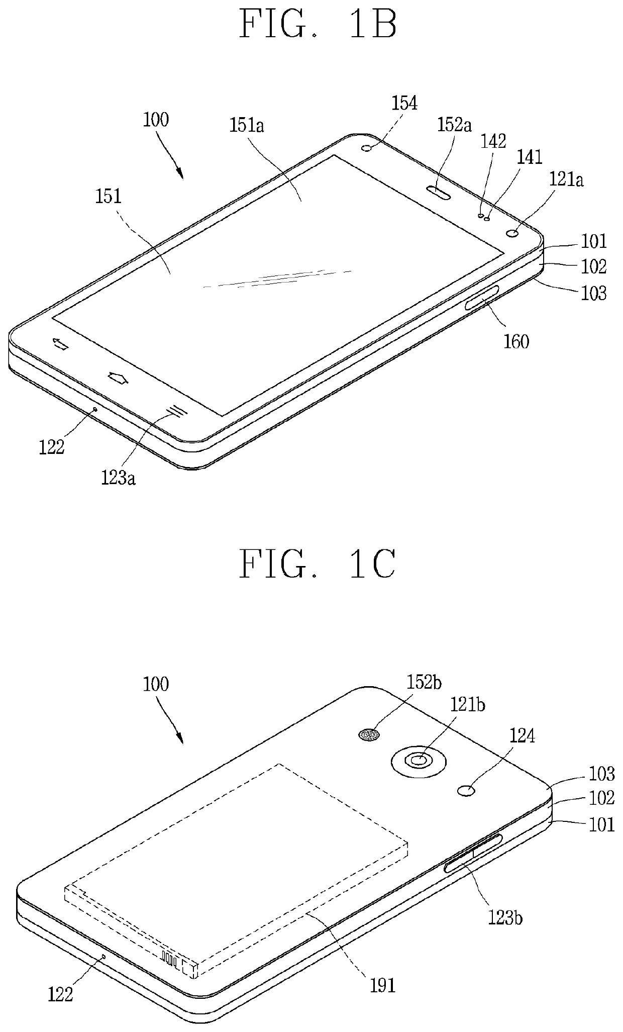
[0046]Hereinafter, preferred embodiments of the present disclosure will be described in detail with reference to the accompanying drawings, and the same or similar elements are designated with the same numeral references regardless of the numerals in the drawings and their redundant description will be omitted. A suffix “module” and “unit” used for constituent elements disclosed in the following description is merely intended for easy description of the specification, and the suffix itself does not give any special meaning or function. In describing the present disclosure, moreover, the detailed description will be omitted when a specific description for publicly known technologies to which the invention pertains is judged to obscure the gist of the present disclosure. The accompanying drawings are used to help easily understand the technical idea of the present disclosure and it should be understood that the idea of the present disclosure is not limited by the accompanying drawings...


PUM


Abstract

A mobile terminal according to the present invention, comprises: a first patch antenna operating in a first frequency band and having a circular or polygonal shape; and a second patch antenna operating in a second frequency band that is higher than the first frequency band and having a shape different from the shape of the first patch antenna, wherein through the patch antennas having different shapes, isolation between the antennas operating in different frequency bands can be improved.

Description

CROSS-REFERENCE TO RELATED APPLICATIONS[0001]This application is the National Stage filing under 35 U.S.C. 371 of International Application No. PCT / KR2018 / 005110, filed on May 2, 2018, which claims the benefit of U.S. Provisional Application No. 62 / 638,971, filed Mar. 6, 2018, the contents of which are all hereby incorporated by reference herein in their entirety.BACKGROUND1. Technical Field[0002]The present disclosure relates to a mobile terminal having an antenna. More specifically, the present disclosure relates to a mobile terminal having antennas operating in different frequency bands.2. Description of the Related Art[0003]Terminals may be classified into mobile / portable terminals and stationary terminals according to their mobility. Furthermore, mobile terminals may be divided into handheld terminals and vehicle mounted terminals according to whether or not it can be directly carried by a user.[0004]The functions of mobile terminals have been diversified. For example, the func...

Claims


Application Information

Patent Timeline
Patent Type & Authority Applications(United States)
IPC IPC(8): H01Q21/06H01Q9/04H01Q1/24H01Q5/35H01Q3/26
CPCH01Q9/045H01Q1/243H01Q21/065H01Q5/35H01Q3/26H01Q5/42H01Q9/0414H01Q1/521H01Q21/24H01Q9/0435H01Q9/0457H01Q21/08H01Q21/28H01Q9/0407H04M1/0202
Inventor RYU, SEUNGWOOLEE, JAEWONLEE, JOOHEEJUNG, JUNYOUNG
Owner LG ELECTRONICS INC
Why Eureka
Try Eureka