
Image forming apparatus

Active Publication Date: 2020-12-31
CANON KK
View PDF0 Cites 2 Cited by
  • Summary
  • Abstract
  • Description
  • Claims
  • Application Information

AI Technical Summary

Benefits of technology

The present invention aims to provide an image forming apparatus that can reduce the size of the development collection unit, which is a mountable and dismountable unit that collects developer.

Problems solved by technology

There arose such a problem.

Method used


Image

  • Image forming apparatus
  • Image forming apparatus
  • Image forming apparatus

Examples


first embodiment

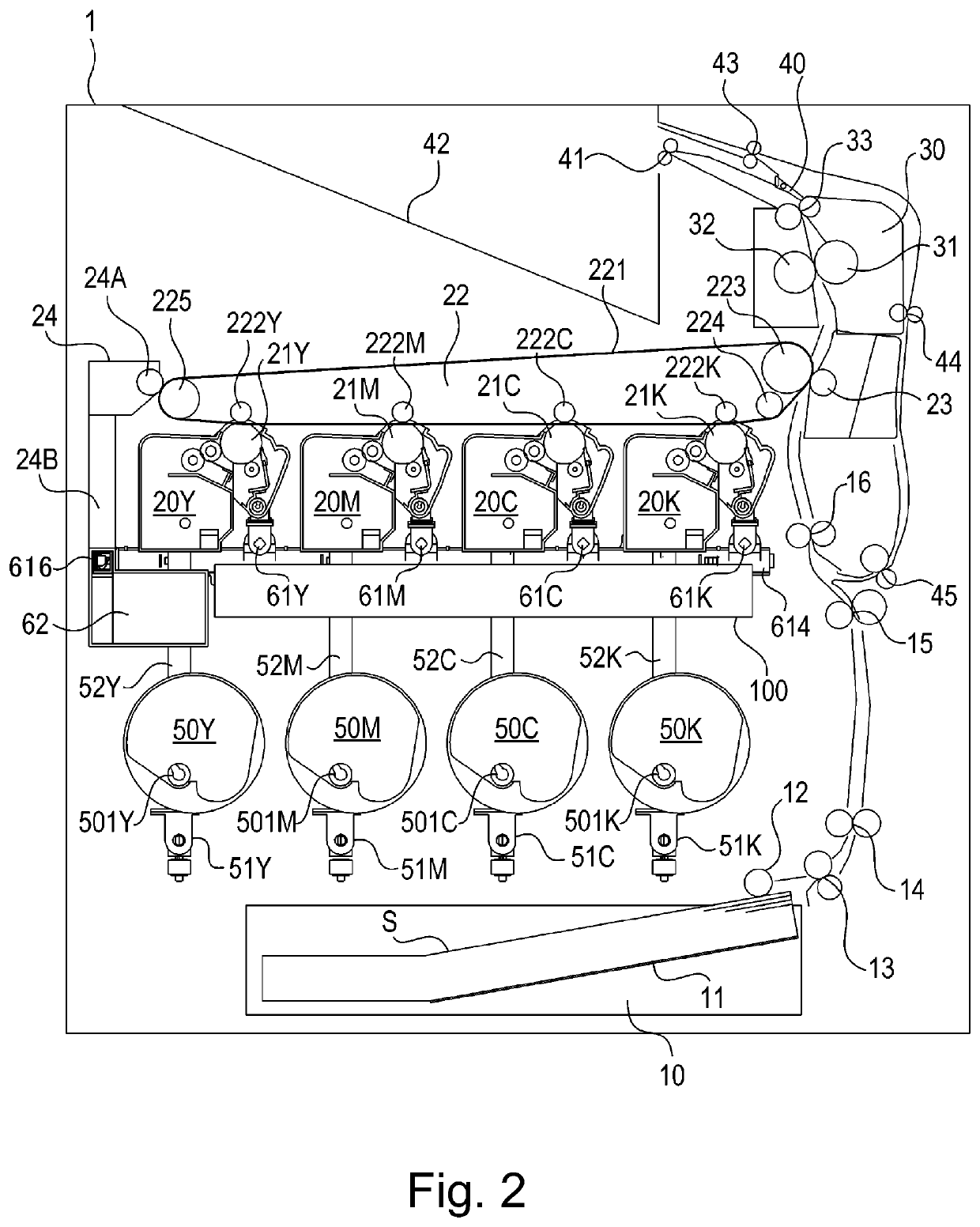
[0021]A general structure of the image forming apparatus will be described by using FIG. 2. FIG. 2 is a sectional view showing an outline of entirety of the image forming apparatus according to the first embodiment. In this embodiment, a color laser printer is used as an example of the image forming apparatus.

Transfer(-Receiving) Material Feeding Portion

[0022]At a lower portion of an image forming apparatus 1, a feeding cassette 10 capable of stacking and accommodating a transfer material is accommodated so as to be pullable. At a downstream-side end portion of the feeding cassette 10 with respect to a transfer material feeding direction, a pick-up roller 12 is provided. In the feeding cassette 10, an intermediary plate 11 for raising an end of the transfer material toward the pick-up roller 12 is provided. A transfer material bundle S including a plurality of transfer materials stacked on the intermediary plate 11 is raised to a position where a surface of an uppermost transfer mat...

second embodiment

[0060]An image forming apparatus according to a second embodiment will be described with reference to FIGS. 7 to 10. FIG. 7 is a sectional view showing an outline of entirety of the image forming apparatus according to the second embodiment. FIG. 8 is a perspective view illustrating a positional relationship between frame members, a developer supplying passage and a developer collecting passage and shows a state in which a process cartridge is dismounted from the image forming apparatus. In this embodiment, a color laser printer is illustrated as the image forming apparatus.

[0061]Incidentally, in the image forming apparatus according to this embodiment, as shown in FIG. 7, separately from a first developer collecting container 62a for collecting a developer removed from an intermediary transfer belt 221, a second developer collecting container 62b for collecting the developer removed from a photosensitive drum 21 is provided. Portions other than this point are substantially the same...


PUM


Abstract

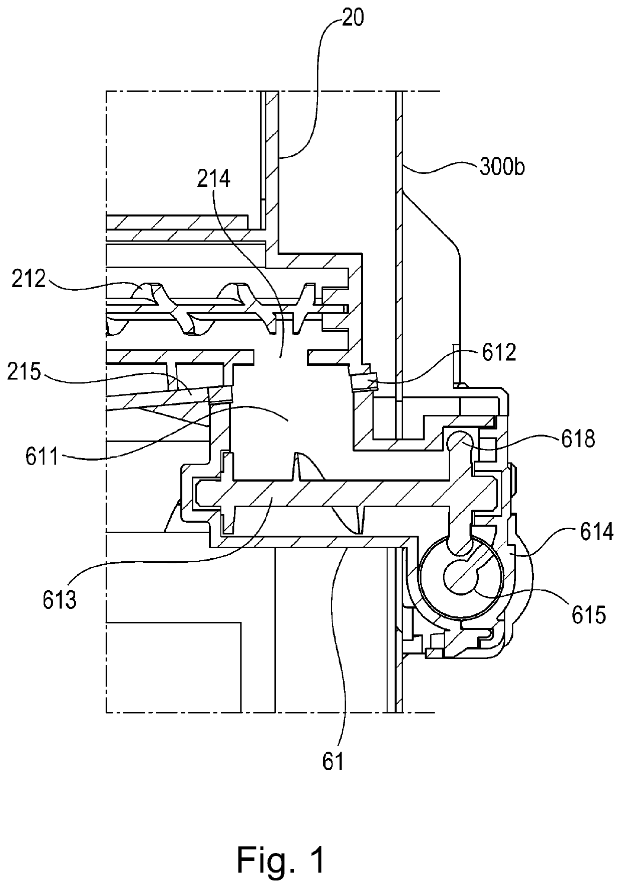
An image forming apparatus includes a photosensitive unit provided with a discharge opening, a pair of frame members, a developer receiving portion connected to the discharge opening, and a developer feeding portion connected to the developer receiving portion. The developer receiving portion is provided inside a space sandwiched between the frame members. The developer feeding portion is provided outside the space.

Description

FIELD OF THE INVENTION AND RELATED ART[0001]The present invention relates to an image forming apparatus, such as a copying machine, a facsimile machine, a printer and a multi-function machine, in which a developer removed from a photosensitive member is discharged and collected.[0002]Conventionally, in an image forming apparatus using the developer, a technique in which the developer generating during image formation is collected in a collecting container and the collecting container is periodically exchanged has been known (Japanese patent No. 4622353).[0003]In this technique, on a drawer provided so as to be pullable from an image forming apparatus main assembly, an image forming unit is mounted, and the drawer on which the image forming unit is mounted is pushed in the image forming apparatus main assembly, so that the image forming unit is mounted in the image forming apparatus. This image forming unit includes a feeding member for feeding the developer in the image forming unit...

Claims


Application Information

Patent Timeline
Patent Type & Authority Applications(United States)
IPC IPC(8): G03G15/08G03G21/00
CPCG03G21/0011G03G21/105G03G2221/1624G03G15/0891G03G15/0865G03G21/12G03G21/1619G03G15/1615G03G15/1625G03G15/1645
Inventor NAKAYASHIKI, YUJI
Owner CANON KK
Learn More