
Duty cycle tuning circuit and method thereof

a duty cycle and tuning circuit technology, applied in the direction of pulse manipulation, pulse technique, digital transmission, etc., can solve the problems of excessively large additional delay, limited application range and output precision of tuning circuit, and difficulty in providing a great tuning range, so as to reduce the unit requirement of delay chain, reduce the effect of delay chain unit requirement and high stability

Active Publication Date: 2015-04-28
REALTEK SEMICON CORP
View PDF14 Cites 1 Cited by
  • Summary
  • Abstract
  • Description
  • Claims
  • Application Information

AI Technical Summary

Benefits of technology

This approach allows for a stable and efficient generation of a 50% duty cycle clock signal with reduced complexity and power consumption, while being less affected by external factors, thus improving the performance and efficiency of the tuning circuit.

Problems solved by technology

However, in this tuning mode, it is difficult to provide a great tuning range (for example, over 10% of the clock cycle of the clock signal).
Although the tuning mode may provide a high tuning precision (for example, 1 ps / step), the application range and the output precision of the tuning circuit are limited.
However, an excessively great additional delay is generally not desired in many applications.
In this case, the problem of the additional delay of the tuning circuit becomes more serious, and the area and the power consumption of the tuning circuit are also increased.
In the case of the great tuning range and the high tuning precision, a great number of unit delay cells are needed, so that the complexity of the tuning circuit is increased significantly, it is also difficult to control the influence of the parasitic effect, and furthermore, the area and the power consumption of the tuning circuit are increased.

Method used


Image

  • Duty cycle tuning circuit and method thereof
  • Duty cycle tuning circuit and method thereof
  • Duty cycle tuning circuit and method thereof

Examples


Embodiment Construction

[0020]The terms “first” and “second” in the following description are used to differentiate elements indicated by the terms, and are not used to indicate a sequence or limit the difference of the elements indicated by the terms, and are not used to limit the protection scope of the present invention.

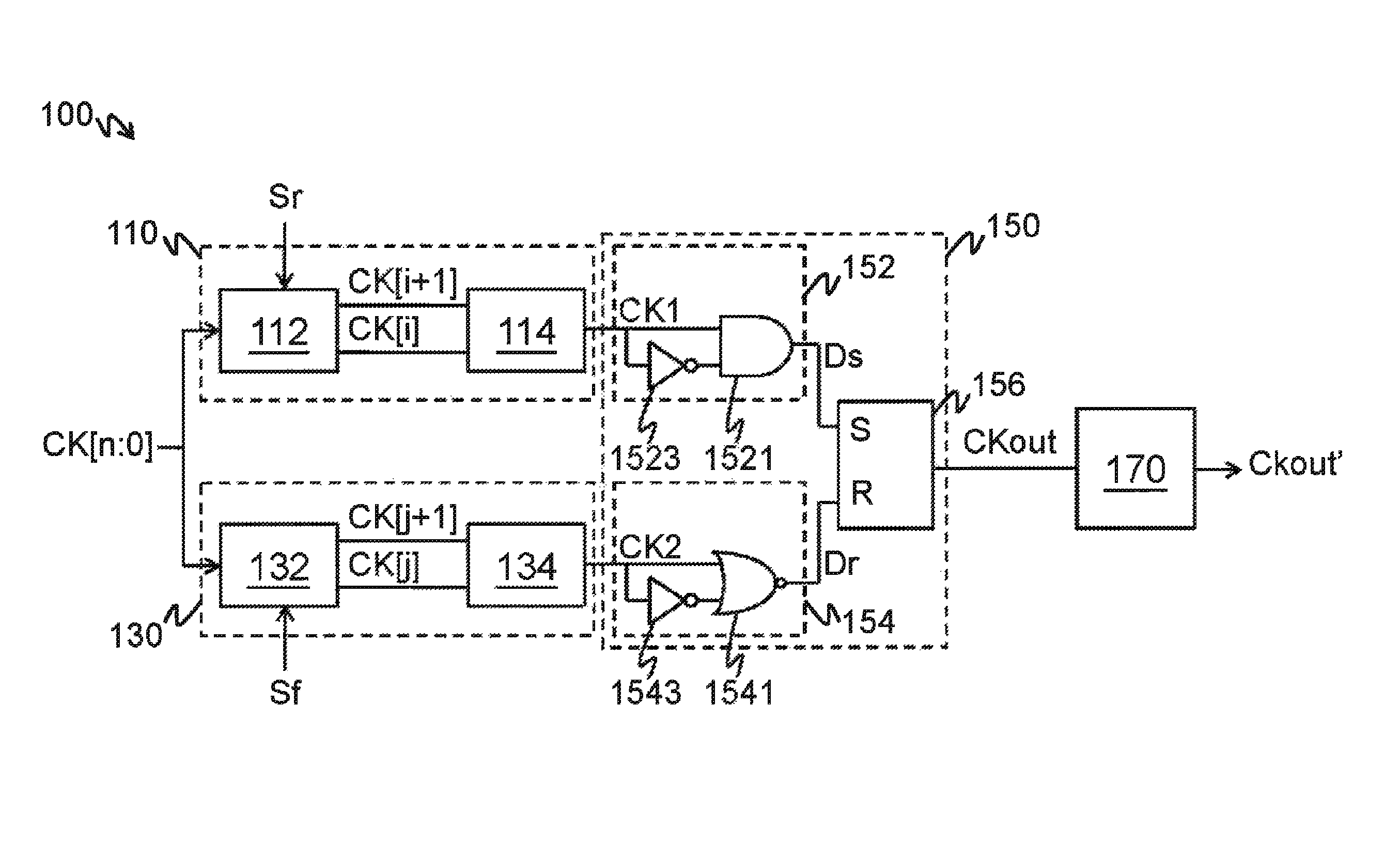
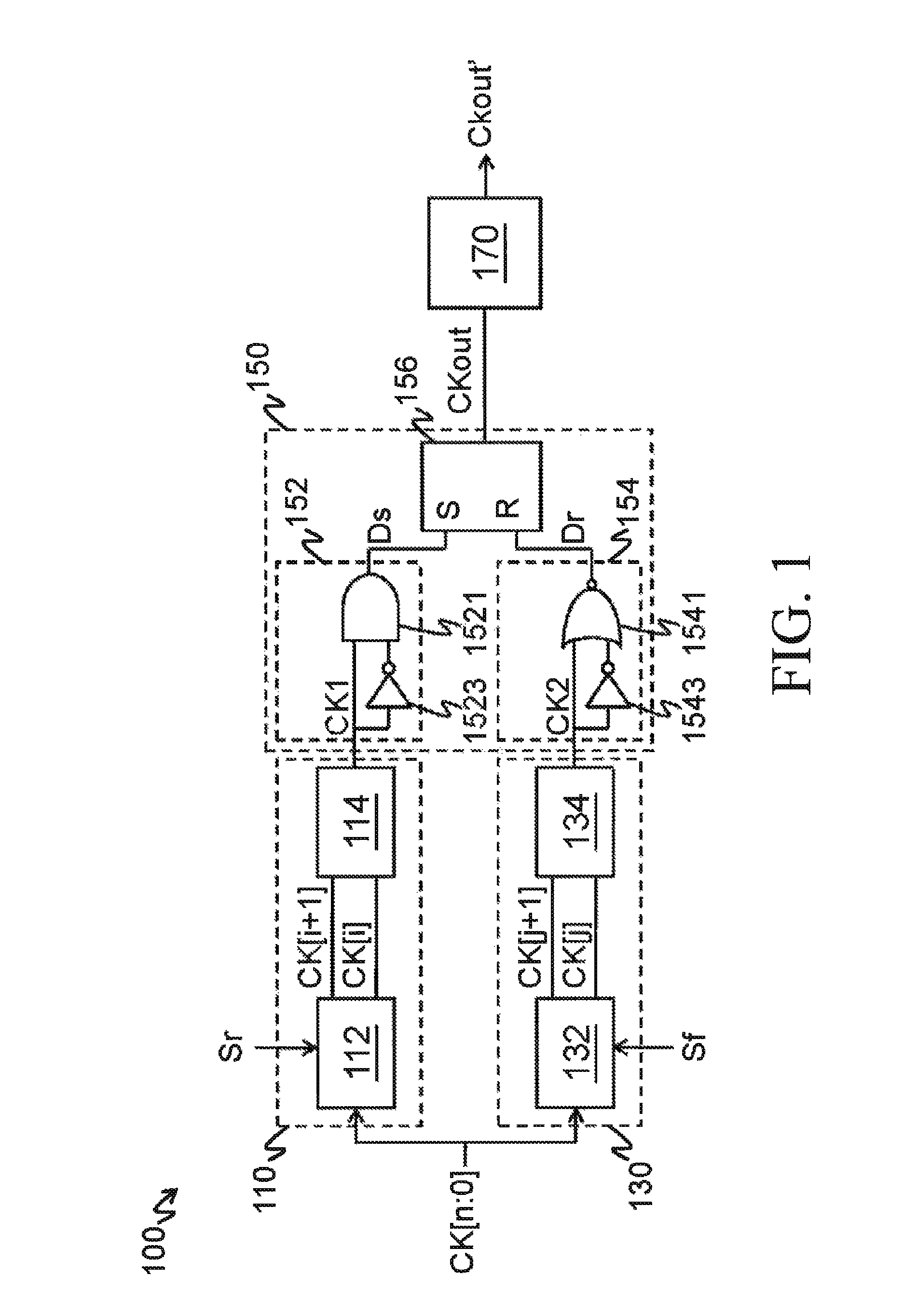
[0021]A duty cycle tuning circuit provided in the present invention includes multiple interpolation circuits, an edge detection circuit, and a delay chain. To facilitate the description, please refer to FIG. 1, the description is made through an embodiment having two interpolation circuits (called a first interpolation circuit 110 and a second interpolation circuit 130).

[0022]The first interpolation circuit 110 is coupled to an input end of the edge detection circuit 150, and the second interpolation circuit 130 is coupled to the other input end of the edge detection circuit 150. A delay chain 170 is connected electrically to the edge detection circuit 150. In this embodiment, the delay ...


PUM


Abstract

A duty cycle tuning circuit and a method thereof are provided, in which the duty cycle tuning circuit includes multiple interpolation circuits, an edge detection circuit, and a delay chain. Each interpolation circuit receives multiple phase clocks, and interpolates an interpolation clock from two of the phase clocks. The phase clocks have the same frequency but different phases. The edge detection circuit is connected electrically to the delay chain, and generates an output clock according to an edge of the interpolation clock.

Description

CROSS-REFERENCES TO RELATED APPLICATIONS[0001]This non-provisional application claims priority under 35 U.S.C. §119(a) on Patent Application No. 2012104228619 filed in China, P.R.C. on Oct. 10, 2012, the entire contents of which are hereby incorporated by reference.BACKGROUND OF THE INVENTION[0002]1. Technical Field[0003]The present invention relates to a technology for generating a clock signal having a 50% duty cycle, and more particularly to a duty cycle tuning circuit and a method thereof.[0004]2. Related Art[0005]In many high-speed and high-performance applications, it is required to provide a clock signal having a 50% duty cycle to a system. For example, in a double data rate synchronous dynamic random-access memory (DDR SDRAM) system, a rising edge and a falling edge of a clock signal are used to process data to achieve an objective that the data transmission rate is increased by 100% in the same clock frequency. In this application, the clock signal must have a precise 50% d...

Claims


Application Information

Patent Timeline
Patent Type & Authority Patents(United States)
IPC IPC(8): H03L7/00H03K5/156
CPCH03K5/1565
Inventor LIU, YE
Owner REALTEK SEMICON CORP
Learn More