
Multipiece v-rail wear strip

a wear strip and multi-piece technology, applied in soil shifting machines/dredgers, constructions, etc., can solve the problems of blades not being effective for their intended purpose, degrading the working edge, and manufacturing the wear strip may be more difficult or more expensive than desired

Active Publication Date: 2021-01-07
CATERPILLAR INC
View PDF0 Cites 0 Cited by
  • Summary
  • Abstract
  • Description
  • Claims
  • Application Information

AI Technical Summary

Benefits of technology

The present patent describes a mounting assembly for attaching a board assembly or blade assembly to a grading machine. The assembly includes a Y-shaped slot jaw member with a horizontal direction and a vertical direction, forming a first wear strip attachment portion and a first angled wear strip support portion. The assembly also includes a v-shaped wear strip with a first attachment portion and a first pressing portion forming a first obtuse angle with the first attachment portion. The assembly allows for easy attachment and detachment of wear strips to the jaw member, and the v-shaped wear strip provides improved holding power for the blade assembly or board assembly.

Problems solved by technology

These blades often encounter abrasive material such as rocks, dirt, etc. that can degrade the working edge, making such blades ineffective for their intended purpose.
Manufacturing the wear strip may be more difficult or more expensive than desired.
As can be seen by looking at the figures of Stubben, the shape of its wear strips require expensive manufacturing such as casting, or machining, etc.

Method used


Image

  • Multipiece v-rail wear strip
  • Multipiece v-rail wear strip
  • Multipiece v-rail wear strip

Examples


Embodiment Construction

[0017]Reference will now be made in detail to embodiments of the disclosure, examples of which are illustrated in the accompanying drawings. Wherever possible, the same reference numbers will be used throughout the drawings to refer to the same or like parts. In some cases, a reference number will be indicated in this specification and the drawings will show the reference number followed by a letter for example, 100a, 100b or a prime indicator such as 100′, 100″ etc. It is to be understood that the use of letters or primes immediately after a reference number indicates that these features are similarly shaped and have similar function as is often the case when geometry is mirrored about a plane of symmetry. For ease of explanation in this specification, letters or primes will often not be included herein but may be shown in the drawings to indicate duplications of features discussed within this written specification.

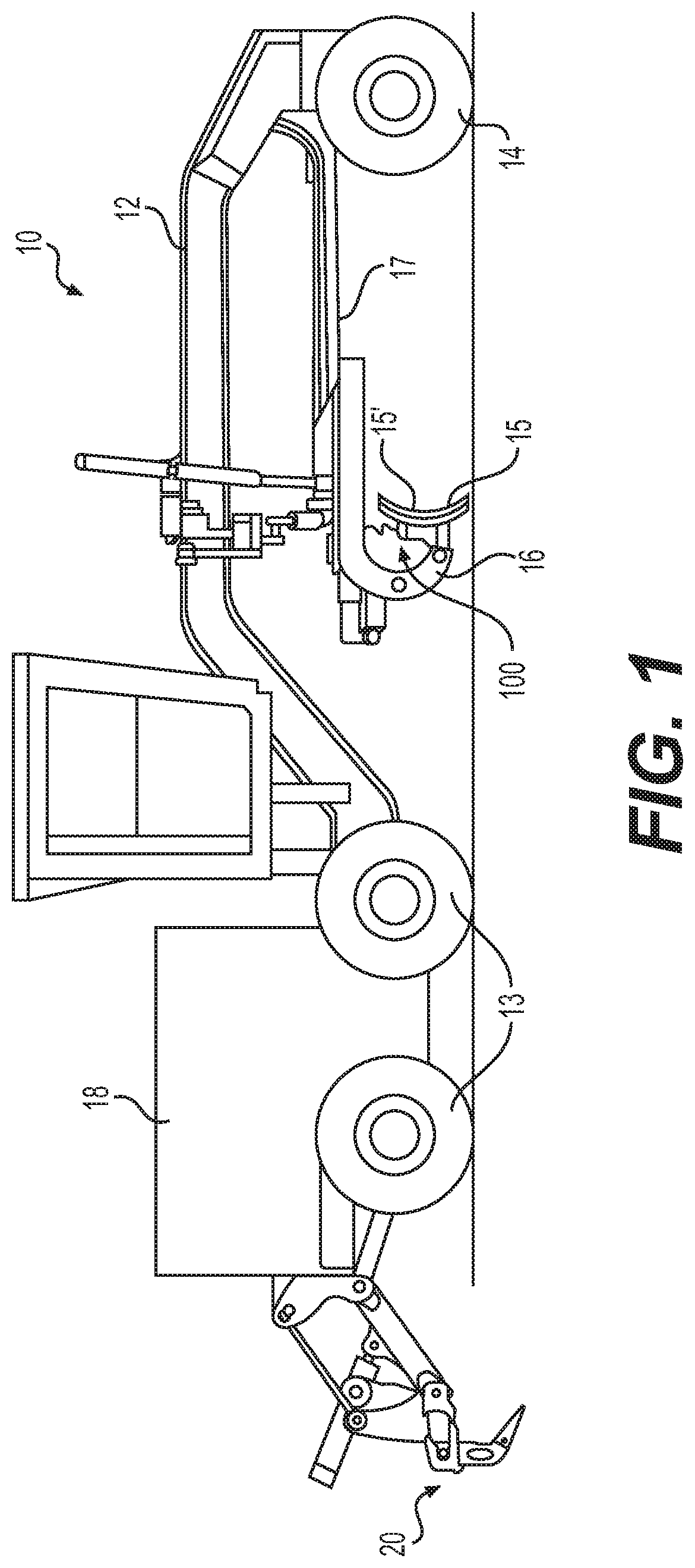
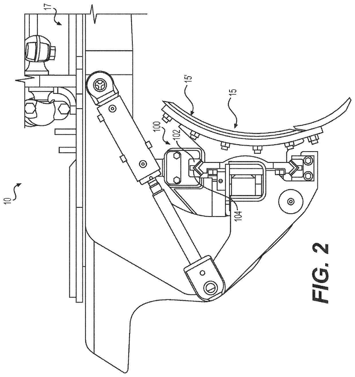
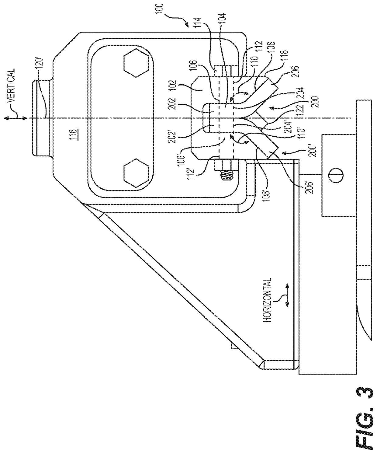
[0018]A mounting assembly that uses v-shaped wear strips for engagi...


PUM


Abstract

A v-shaped wear strip includes a v-shaped body defining a longitudinal axis, a first end, and a second end disposed along the longitudinal axis. The v-shaped body includes a first attachment portion defining a first aperture, a first pressing portion that forms a first oblique angle with the first attachment portion at the first end, and a first arcuate portion transitioning from the first attachment portion to the first pressing portion at the first end.

Description

TECHNICAL FIELD[0001]The present disclosure relates to mounting assemblies for attaching scarifier boards or blades used by motor graders or other similar equipment to the machine. More specifically, the present disclosure relates to wear strips that facilitate the attachment of a board assembly or a blade assembly to the machine.BACKGROUND[0002]Machines such as motor graders employ a long blade that is used to level work surfaces during the grading phase of a construction project or the like. These blades often encounter abrasive material such as rocks, dirt, etc. that can degrade the working edge, making such blades ineffective for their intended purpose. Accordingly, it is desirable to mount or demount the blade to facilitate replacement of the blade or changing the type of blade attached to the machine when using the machine in different applications.[0003]Various systems have been employed to attach the board or blade to the machine. In many cases, an upper jaw and a lower jaw ...

Claims


Application Information

Patent Timeline
Patent Type & Authority Applications(United States)
IPC IPC(8): E02F3/815E02F9/28
CPCE02F3/8157E02F9/2883E02F3/7636
Inventor VAHLING, BRUCE RAYMONDHARSHMAN, NATHANIEL KEITH
Owner CATERPILLAR INC
Learn More