Determination of rheology of fluid in an oil or gas well

Active Publication Date: 2021-01-07
CONOCOPHILLIPS CO
View PDF0 Cites 2 Cited by
  • Summary
  • Abstract
  • Description
  • Claims
  • Application Information

AI Technical Summary

Benefits of technology

[0011]The inventor(s) have appreciated that, if real-time data about rheology at downhole conditions were available, it could allow for “real time” fine tuning of the fluid and increase confidence in the progress of a downhole operation such as drilling. It could decrease risks in the drilling process as operators would have a much better grasp on the hole cleaning and on likelihood of sag, both static sag and

Problems solved by technology

Currently, old data tends to be used, and this can lead

Method used


Image

  • Determination of rheology of fluid in an oil or gas well
  • Determination of rheology of fluid in an oil or gas well
  • Determination of rheology of fluid in an oil or gas well

Examples


first embodiment

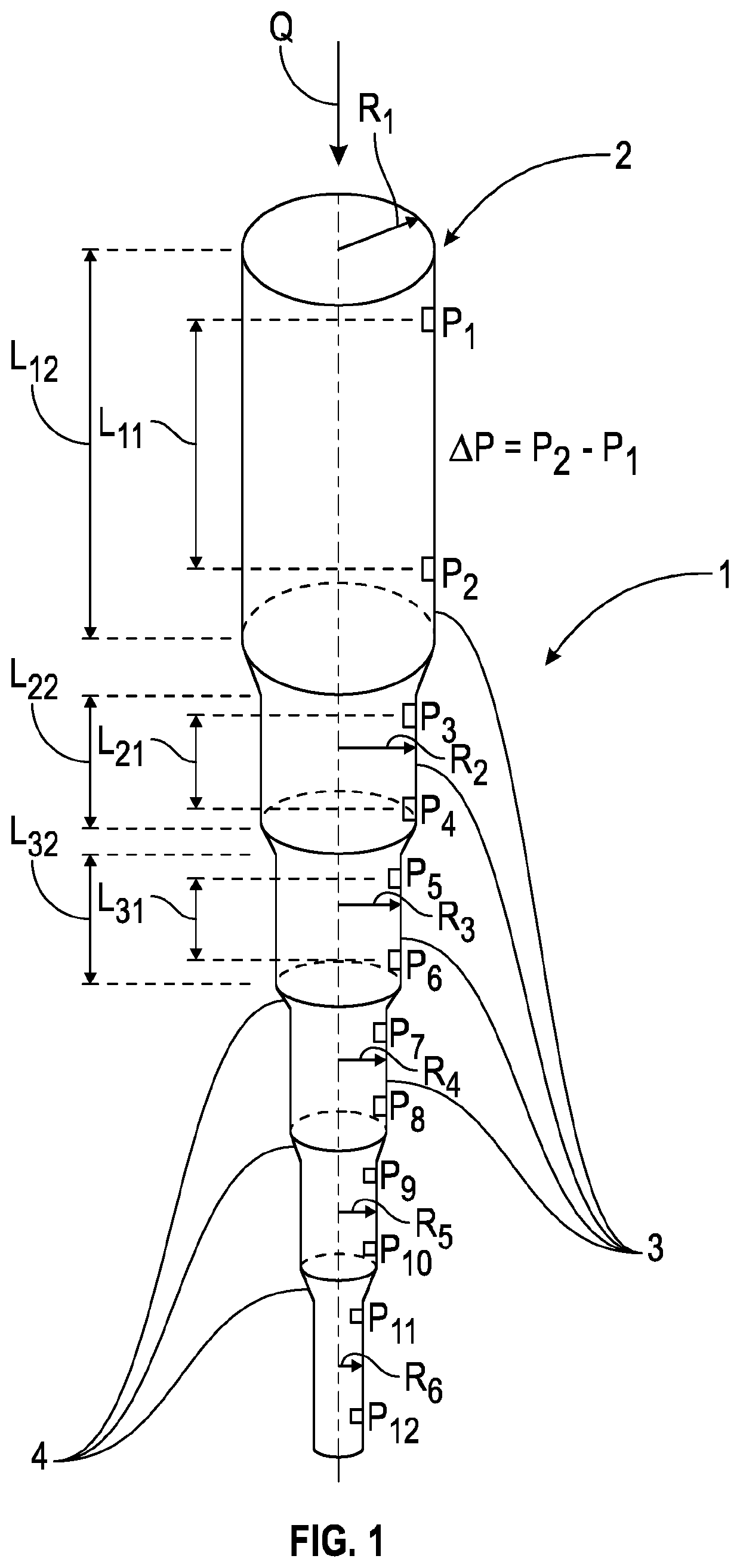
[0033]As shown in FIG. 1, sensor apparatus is shown. The apparatus 1 is designed to measure parameters related to the rheology of drilling mud comprises a tube 2 having a number of sections 3 each with a different internal diameter R1, R2, etc. Pressure sensors P1 to P12 are located along the length of the tube, with two sensors in each tube section 3 which are spaced apart along the length of the tube section.

[0034]The sections 3 are of decreasing diameter in the intended direction of flow of fluid (see arrow Q1). Between the sections 3 are transition regions 4 of gradually changing diameter. Each section 3 has a length L12, L22, L32, etc, whilst the distance between the sensor pairs in each section 3 is referenced L11, L21, L31, etc. The exact dimensions of the device have not yet been determined but the overall length is likely to be a few metres in length, e.g. 2 to 10 metres.

[0035]The device is designed to be installed in the internal bore of a drillstring, through which drilli...

second embodiment

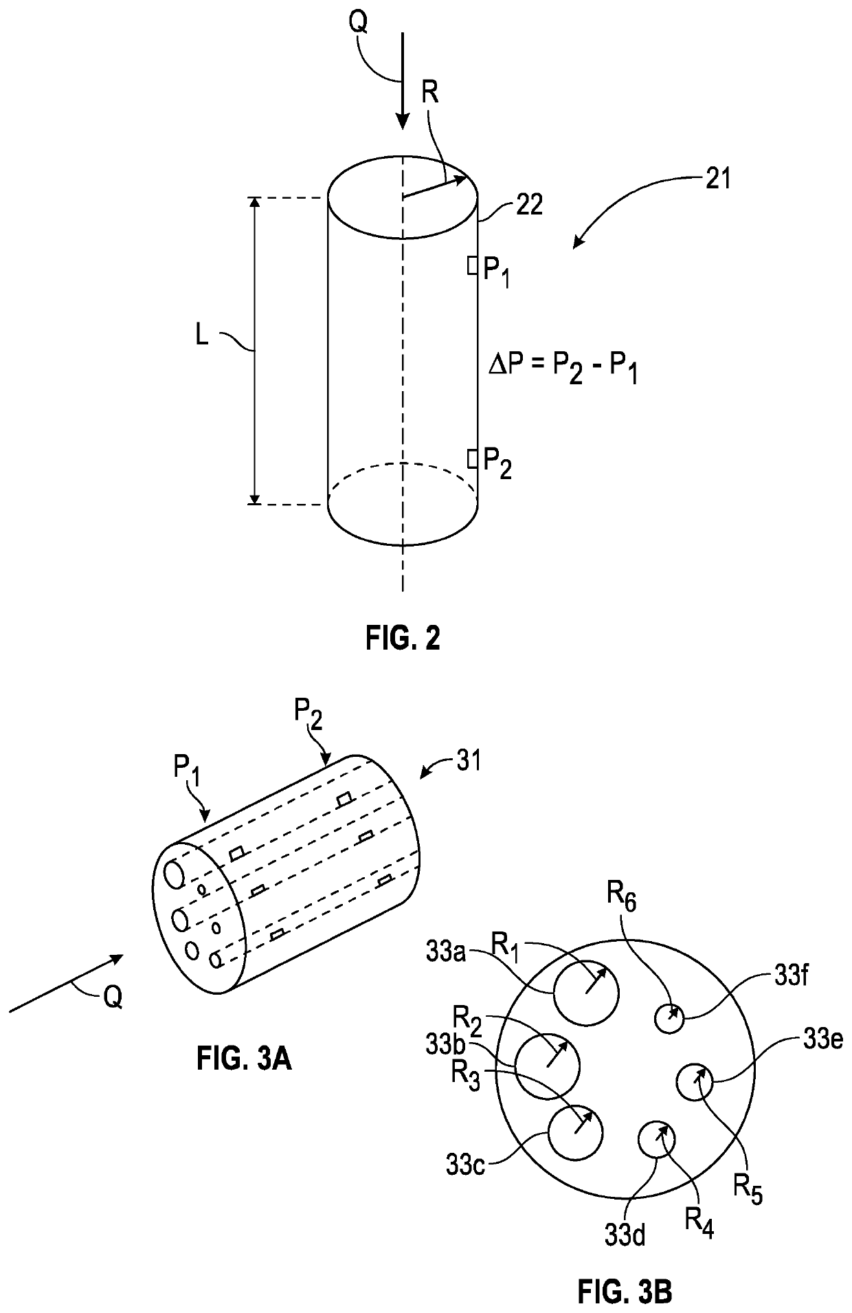
[0044]sensor apparatus 21 is shown in FIG. 2. This embodiment is simpler than the first, comprising simply a tube 22 of constant diameter with an upstream and downstream pressure sensor P1 and P2. This embodiment, like the first, would be mounted in a BHA. However, this embodiment would require the flow rate of drilling fluid through the device to be varied in order to give readings for different shear stress equivalent to the r.p.m. settings of, e.g., a Fann 75 device. This could be arranged by having a separate pumping apparatus associated with the tool, by having an adjustable flow diverter device, or by varying the drilling fluid flow rate through the drillstring from the wellhead pump. In the latter case, a disadvantage would be that continuous sensing of fluid properties would not be possible, since normal operations would have to be suspended for a period in order to vary the drilling fluid flow rate.

[0045]A third embodiment of sensor 31 is shown in FIGS. 3a and 3b. This embo...


PUM


Abstract

The invention relates to the measurement of the rheology of drilling fluid down a hydrocarbon well in real time during operations. A sensor device comprising a pipe rheometer with multiple diameters is installed in a bottom hole assembly tool, such that a portion of the total flow of drilling fluid passes through it. In this way the rheological properties of the drilling fluid can be determined under the high pressures and elevated temperatures encountered downhole.

Description

CROSS-REFERENCE TO RELATED APPLICATIONS[0001]This application is a non-provisional application which claims benefit under 35 USC § 119(e) to U.S. Provisional Application Ser. No. 62 / 870,290 filed Jul. 3, 2019, entitled “DETERMINATION OF RHEOLOGY OF FLUID IN AN OIL OR GAS WELL,” which is incorporated herein in its entirety.STATEMENT REGARDING FEDERALLY SPONSORED RESEARCH OR DEVELOPMENT[0002]None.FIELD OF THE INVENTION[0003]This invention relates to the measurement and analysis of the properties of certain fluids in an oil or gas well.BACKGROUND OF THE INVENTION[0004]When drilling an oil or gas (hydrocarbon) well or performing some other operations downhole in a hydrocarbon well, it is desirable to understand the properties of any fluids in the well. Such fluids can include Synthetic and Oil-based drilling mud, or mixtures of these. These fluids are non-Newtonian and their properties can be hard to predict under downhole conditions of high pressure and elevated temperature.[0005]For e...

Claims


Application Information

Patent Timeline
IPC IPC(8): E21B21/08E21B49/08
CPCE21B21/08E21B49/08E21B47/06G01N11/08G01N2011/0026
Inventor NESHEIM, GUNVALD
Owner CONOCOPHILLIPS CO
Why Eureka
Try Eureka