Display apparatus
a technology of display apparatus and display screen, which is applied in the direction of transducer diaphragm, instruments, casings/cabinets/drawer details, etc., can solve the problems of deteriorating immersion of viewers, difficult to accurately provide sound to viewers, and limitation of conventional display apparatus, so as to improve sound quality and improve sound quality
- Summary
- Abstract
- Description
- Claims
- Application Information
AI Technical Summary
Benefits of technology
Problems solved by technology
Method used
Image
Examples
first embodiment
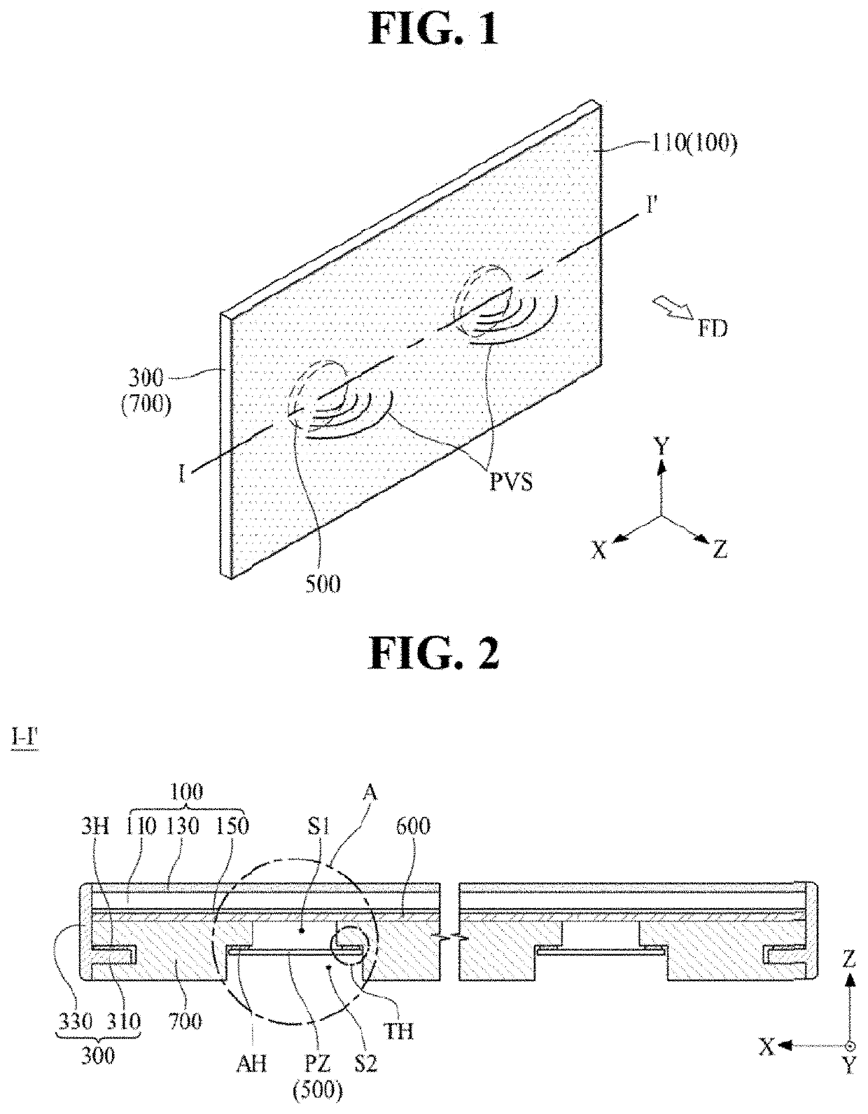
[0065]FIG. 2 is a cross-sectional view, cutting along I-I′ in FIG. 1, illustrating a structure of the display apparatus according to the first embodiment of the present disclosure. When it is necessary, it will be described with reference to FIG. 1 showing the overall structure of the display apparatus according to the present disclosure.
[0066]Referring to FIG. 2, a display apparatus according to the first embodiment of the present disclosure may comprise a display module 100, a back cover 700 and a sound generating unit 500. The sound generation unit 500 may be implemented as a piezo vibration unit (or piezoelectric vibration unit) PZ suitable for mounting inside the back cover 700 which may be coupled to the rear surface of the display module 100. For example, a piezo element or an electrical active material (EAM) may be used for the sound generating unit 500.
[0067]The display module 100 may include a display panel 110, a functional film 130 and a heat diffusion element 150. The d...
second embodiment
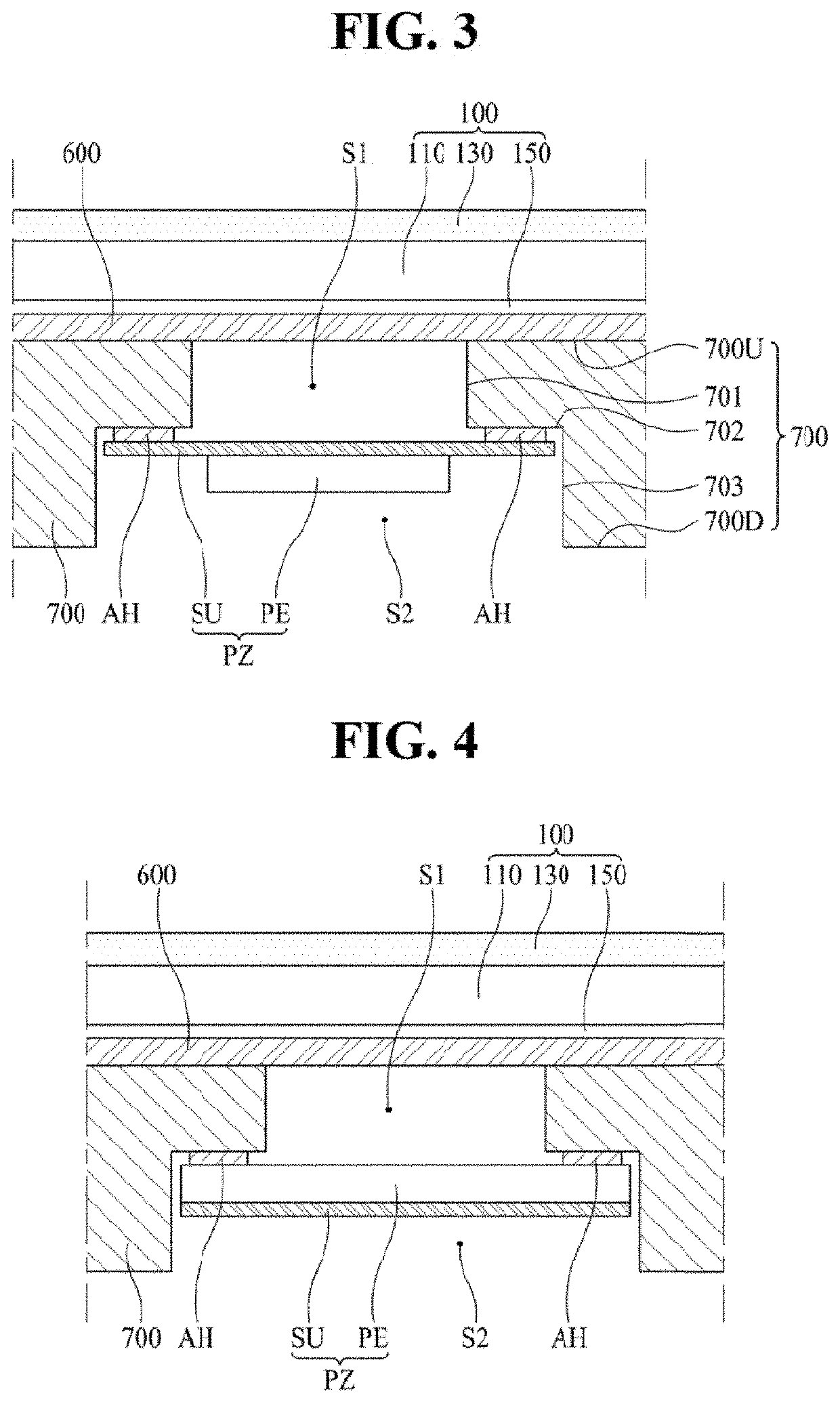
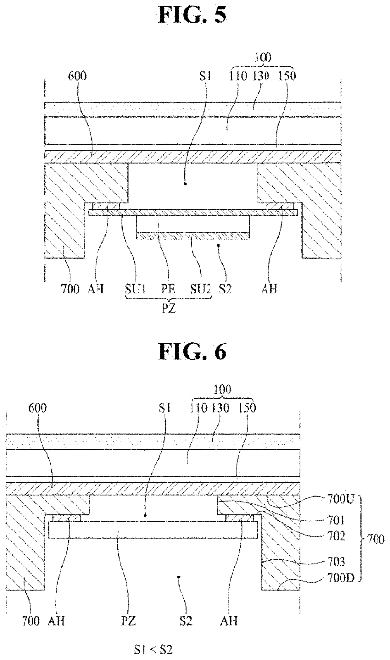
[0099]FIG. 3 is an enlarged cross-sectional view illustrating a structure of a display apparatus according to the second embodiment of the present disclosure. FIG. 3 is an enlarged view of a portion indicated by circle A in FIG. 1. Hereinafter, the main configuration of the second embodiment will be mainly explained. The configurations not shown in FIG. 3 may be referred to FIGS. 1 and 2.
[0100]Referring to FIG. 3, the display apparatus according to the second embodiment of the present disclosure may comprise a display module 100, a back cover 700 and a piezo vibration unit PZ. The display module 100 may be same as the first embodiment, so detail explanation will not be duplicated.
[0101]The back cover 700 may be also same with the first embodiment, excepting the detailed structures of the penetration S1 and the depression S2. The back cover 700 may include a penetration S1 and a depression S2. The depression S2 may have a well shape in which some depths from the rear surface 700D of ...
third embodiment
[0112]FIG. 4 is an enlarged cross-sectional view illustrating a structure of a display structure according to the third embodiment of the present disclosure. FIG. 4 is an enlarged view of a portion indicated by circle A in FIG. 1. Hereinafter, main element of the third embodiment will be explained. For the elements not shown in FIG. 4, FIGS. 1 to 3 may be referred.
[0113]Referring to FIG. 4, the display apparatus according to the third embodiment of the present disclosure may comprise a display module 100, a back cover 700 and a piezo vibration unit PZ. The display module 100 may be same as the first embodiment, so detail explanation will not be duplicated.
[0114]In the third embodiment, the piezo vibration unit PZ may include a piezo vibrator PE and a metal substrate SU. The piezo vibrator PE may be disposed at the middle surface 702 between the depression S2 and the penetration S1 formed inside of the back cover 700. For example, using an adhesive element AH, the piezo vibrator PE m...
PUM
 Abstract
Description
Claims
Application Information
 - R&D
- Intellectual Property
- Life Sciences
- Materials
- Tech Scout
- Unparalleled Data Quality
- Higher Quality Content
- 60% Fewer Hallucinations
Browse by: Latest US Patents, China's latest patents, Technical Efficacy Thesaurus, Application Domain, Technology Topic, Popular Technical Reports.
© 2025 PatSnap. All rights reserved.Legal|Privacy policy|Modern Slavery Act Transparency Statement|Sitemap|About US| Contact US: help@patsnap.com


