
Real-time scan point homogenization for terrestrial laser scanner

a laser scanner and real-time scanning technology, applied in the field of 3d laser scanner time, can solve problems such as visual artifacts and other disturbances, visual artifacts and rendering issues,

Active Publication Date: 2021-01-14
FARO TECH INC
View PDF0 Cites 2 Cited by
  • Summary
  • Abstract
  • Description
  • Claims
  • Application Information

AI Technical Summary

Benefits of technology

This patent describes a 3D measuring device that can create a point cloud that represents multiple surfaces in an environment. The device uses spherical coordinates to determine the location of scan points, which are then filtered to create a smooth representation of the surface. The device can store or discard each scan point based on its value, resulting in a precise and accurate representation of the environment. The technical effect of this invention is a more efficient and accurate method for measuring the shape of multiple surfaces in an environment.

Problems solved by technology

Technical challenges for existing 3D scanners include that of a variable scan-point density in point clouds that are captured, particularly when the scan point density is not a true representation of the physical reality in the environment being captured, or when the variation in the scan point density is introduced by the measurement process / apparatus.
Such variance in the scan-point density can lead to incorrect registration of the point clouds, which in turn can cause visual artifacts and other disturbances when displaying / rendering the point clouds.
The density variations can cause visual artifacts and rendering-issues even prior to registration.

Method used


Image

  • Real-time scan point homogenization for terrestrial laser scanner
  • Real-time scan point homogenization for terrestrial laser scanner
  • Real-time scan point homogenization for terrestrial laser scanner

Examples


Embodiment Construction

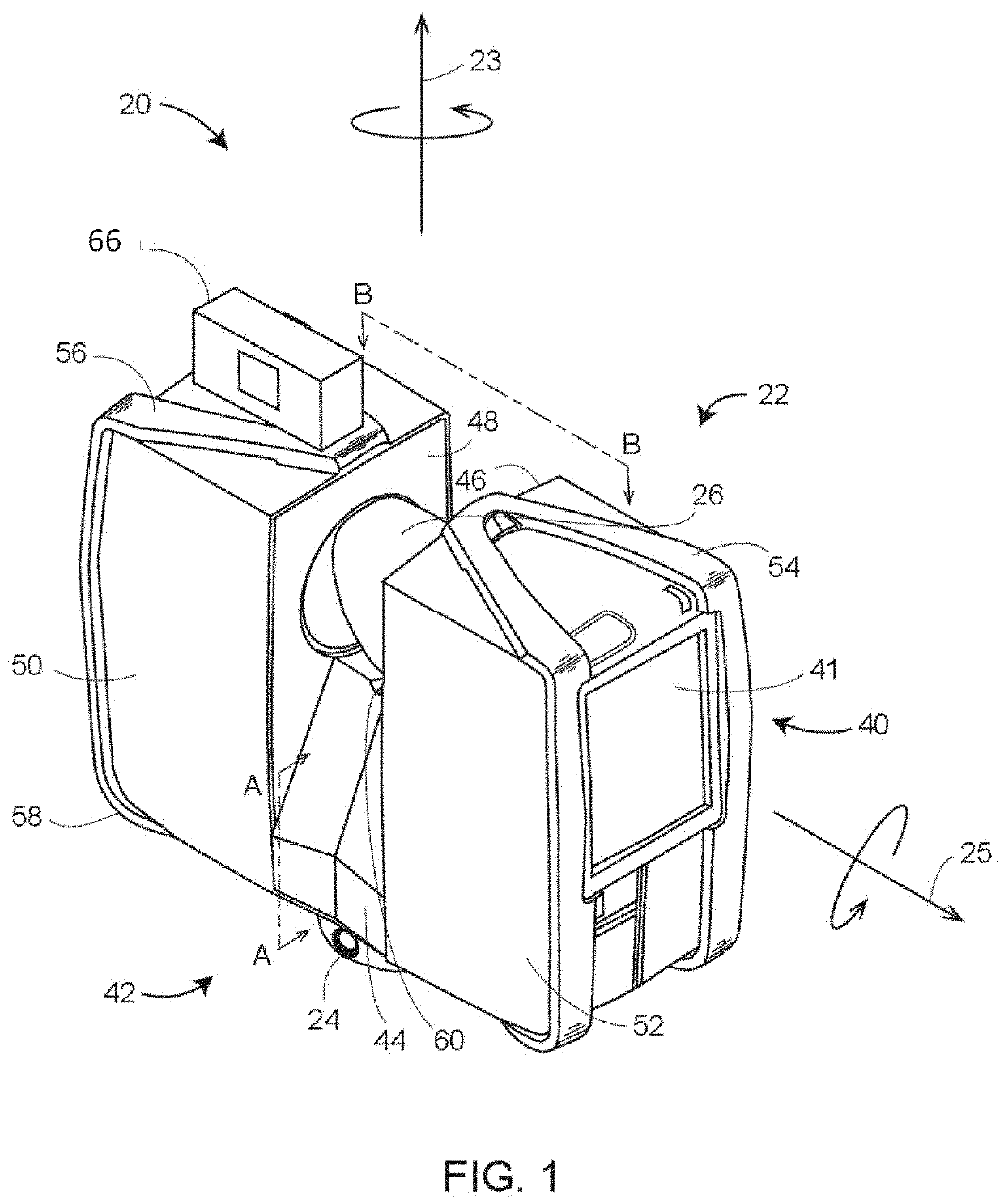
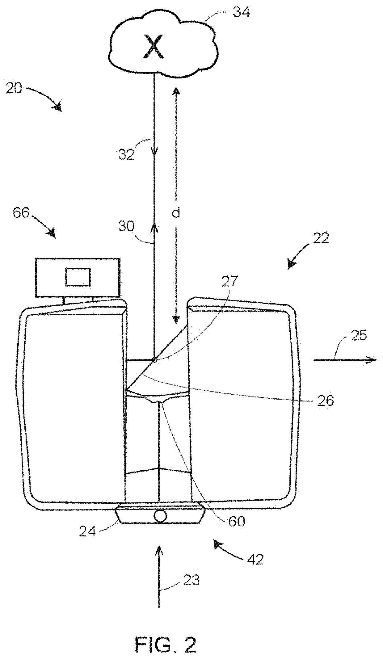
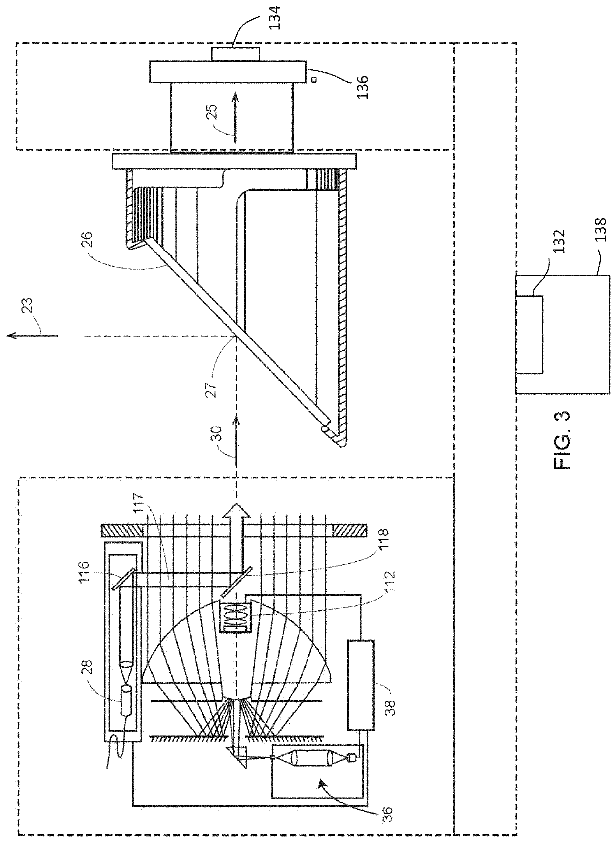
[0023]The present invention relates to a 3D measuring device having a 3D scanner. Embodiments of the invention provide advantages acquiring three-dimensional (3D) coordinates of an area of the environment with real-time sub-sampling of a stream of scan point data as the 3D scanner is capturing a point cloud. Embodiments of the invention provide advantages in acquiring 3D such point clouds using a constant amount of memory, and a constant computational complexity per scan point. Further, the sub-sampling is performed to obtain a homogenized scan point density in the point clouds that are captured. For example, the sub-sampling performed can result in a predetermined density of scan points on surfaces that are orthogonal to the direction of incidence of a measurement beam that is transmitted by the 3D scanner. In one or more examples, the density of scan points can be limited / bounded to a predetermined density because of finite angular resolution. Further, the incidence of the measure...


PUM


Abstract

According to one embodiment, a three-dimensional (3D) measuring device is provided. The 3D measuring device includes a processor system that is configured to generate a point cloud representing multiple surfaces. The point cloud includes multiple scan points. Generating the point cloud includes receiving spherical coordinates for a scan point, the spherical coordinates comprising a distance (r), a polar angle (θ), and an azimuth angle (φ). Generating the point cloud further includes homogenizing a scan point density of the surfaces by filtering the scan points. The homogenizing includes computing a value (p) for the scan point based on the spherical coordinates. Based on the value exceeding a predetermined threshold, storing the scan point as part of the point cloud, and based on the value not exceeding the predetermined threshold, discarding the scan point.

Description

BACKGROUND[0001]The subject matter disclosed herein relates to use of a 3D laser scanner time-of-flight (TOF) coordinate measurement device. A 3D laser scanner of this type steers a beam of light to a non-cooperative target such as a diffusely scattering surface of an object. A distance meter in the device measures a distance to the object, and angular encoders measure the angles of rotation of two axles in the device. The measured distance and two angles enable a processor in the device to determine the 3D coordinates of the target.[0002]A TOF laser scanner is a scanner in which the distance to a target point is determined based on the speed of light in air between the scanner and a target point. Laser scanners are typically used for scanning closed or open spaces such as interior areas of buildings, industrial installations and tunnels. They may be used, for example, in industrial applications and accident reconstruction applications. A laser scanner optically scans and measures o...

Claims


Application Information

Patent Timeline
IPC IPC(8): G01B11/00G01B9/02
CPCG01B11/002G01B9/02041G01B9/0209G01B9/02015G01S17/89G01S17/42G01S7/4817G01C15/002G01S17/86
Inventor BECKER, JULIANPOMPE, DANIEL
Owner FARO TECH INC
Learn More