Gate driver and power converter

a technology of power converter and driver, which is applied in the direction of electronic switching, emergency protective circuit arrangement, pulse technique, etc., can solve the problems of power conversion efficiency decline, increased switching loss at turn-off, and increased cooling element size of the cooling element used to cool the switching elemen

Active Publication Date: 2021-01-14
FUJI ELECTRIC CO LTD
View PDF0 Cites 4 Cited by
  • Summary
  • Abstract
  • Description
  • Claims
  • Application Information

AI Technical Summary

Benefits of technology

[0010]In the present disclosure, there is provision of a gate driver including a drive circuit configured to drive a gate of a switching element connected between a high electric potential output of a power supply and a low electric potential output of the power supply, in accordance with an input signal indicating a command to turn on or to turn off the switching element; a switch-off surge detection circuit configured to detect switch-off surge that occurs in the switching element; a time storing circuit configured to store a time width from a time when the input signal is switched to a command to turn off the switching element to a time when the switch-off surge detection circuit detects occurrence of the switch-off surge; a switching determination circuit configured to determine whether or not to switch a gate driving condition of the switching element, in accordance with a detected value of power supply voltage, the power supply voltage being a potential difference between the high electric potential output of the power supply and the low electric potential output of the power supply; and a driving condition switching circuit configured to switch the gate driving condition in response to a determination by the switching determination circuit to switch the gate driving condition. The gate driving condition is switched when a time corresponding to the time width stored at a previous turn-off of the switching element is elapsed, after a current turn-off of the switching element is started.

Problems solved by technology

Therefore, a gate driver that drives a gate of a switching element connected between a high potential output and a low potential output of a power supply must be designed such that switch-off surge voltage does not exceed withstand voltage of the switching element even if maximum main current flows at maximum power supply voltage.
Therefore, when the power supply voltage Vd is lowered relative to the maximum value, switching losses at turn-off increase compared to a case such as FIG. 1 in which the gate driving condition is not switched.
As a result, for example, there is a risk that power conversion efficiency may decrease or a size of cooling element used to cool the switching element may become larger.

Method used


Image

  • Gate driver and power converter
  • Gate driver and power converter
  • Gate driver and power converter

Examples


Embodiment Construction

[0017]Hereinafter, embodiments according to the present disclosure will be described with reference to the drawings.

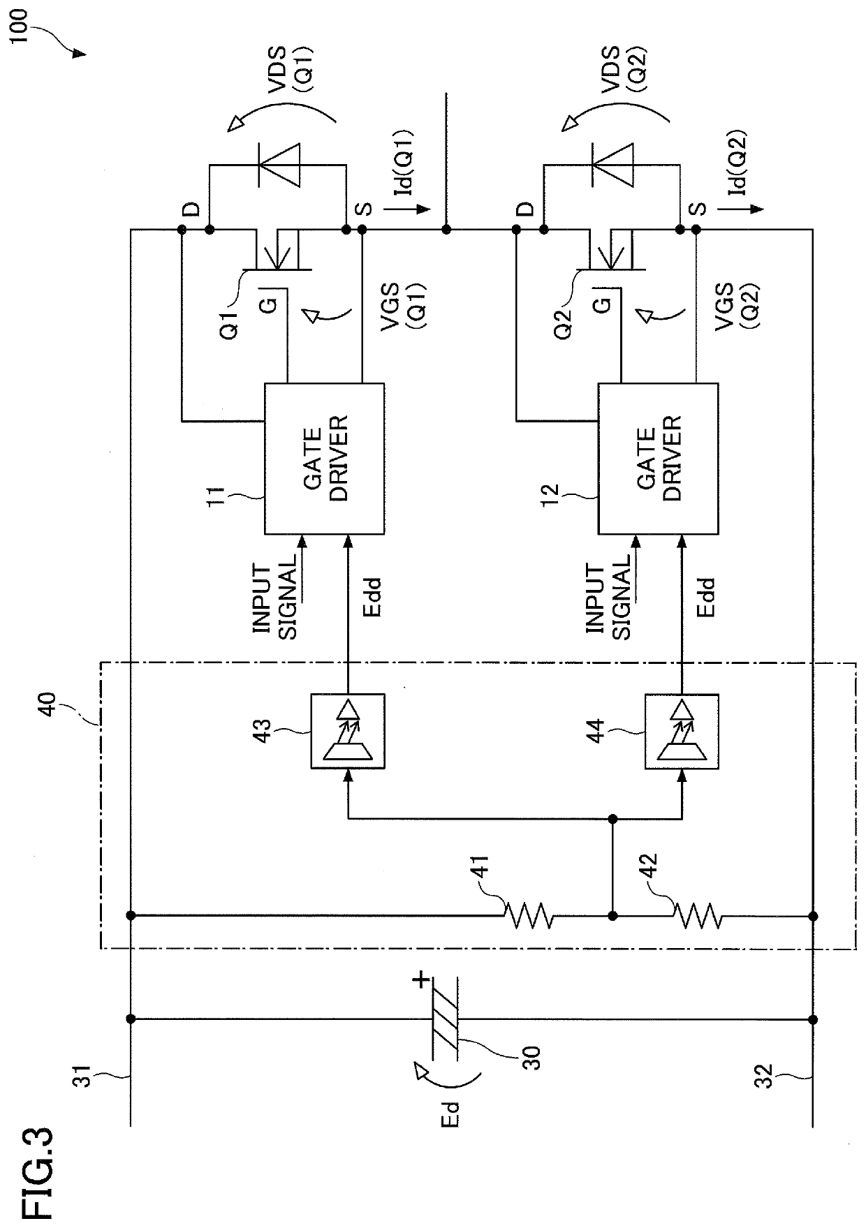
[0018]FIG. 3 is a diagram illustrating an example of a configuration of a power converter. The power converter 100 illustrated in FIG. 3 is a device that converts DC input power to a desired DC or AC output power using a switching element Q1 at a high-side and a switching element Q2 at a low-side. A load (not illustrated) is connected to a connection point between the switching element Q1 and the switching element Q2. The power converter 100 includes a high electric potential output of power supply 31, a low electric potential output of power supply 32, a capacitor 30, the switching elements Q1 and Q2, a power supply voltage detection circuit 40, and gate drivers 11 and 12. The high electric potential output of power supply 31 may also be referred to as a “high power supply potential output 31”, and the low electric potential output of power supply 32 may also be refer...


PUM


Abstract

A gate driver for driving a gate of a switching element in accordance with an input signal is provided. The gate driver is configured to change a gate driving condition in accordance with a detected value of power supply voltage. Each time when the switching element is turned off, the gate driver stores a time width from a time when the input signal is switched to an off command to a time when switch-off surge occurs in the switching device. If it is determined that the gate driving condition should be changed during turn-off operation of the switching element, the gate driver switches the gate driving condition when a time corresponding to the time width stored at a previous turn-off is elapsed after a current turn-off of the switching element is started.

Description

CROSS-REFERENCE TO RELATED APPLICATION[0001]This patent application is based on and claims priority to Japanese Patent Application No. 2019-126959 filed on Jul. 8, 2019, the entire contents of which are incorporated herein by reference.BACKGROUND OF THE INVENTION1. Field of the Invention[0002]The present invention relates to a gate driver and a power converter.2. Description of the Related Art[0003]Conventionally, in order to reduce surge voltage and switching losses, an active gate drive technique is known, in which switching speed is changed at an appropriate timing in accordance with drain current or collector current (hereinafter, referred to as main current) flowing through a switching element. For example, Patent Document 1 discloses a gate drive circuit that stores a length of time (surge period) from a time when a turn-off command for turning off a switching element is issued to a time of occurrence of voltage surge. When the switching element is to be turned off, the gate d...

Claims


Application Information

Patent Timeline
Patent Type & Authority Applications(United States)
IPC IPC(8): H02M1/08H03K17/0412
CPCH02M1/08H02M2001/0054H03K17/04123H02M1/088H02M3/1584H02H7/1213H02M1/0038H02M1/0054H02M3/158H03K17/165H03K17/0822Y02B70/10
Inventor MATSUBARA, KUNIONAGANO, TSUYOSHI
Owner FUJI ELECTRIC CO LTD
Why Eureka
Try Eureka