Tankless Water Heater System
a tankless water heater and tankless technology, applied in water heaters, ohmic-resistance heating, lighting and heating apparatus, etc., can solve the problems of increasing the scalding risk, aggravated problems, and enormous scalding risk for users, so as to avoid scalding and achieve the effect of precise temperature ris
- Summary
- Abstract
- Description
- Claims
- Application Information
AI Technical Summary
Benefits of technology
Problems solved by technology
Method used
Image


Examples
Embodiment Construction
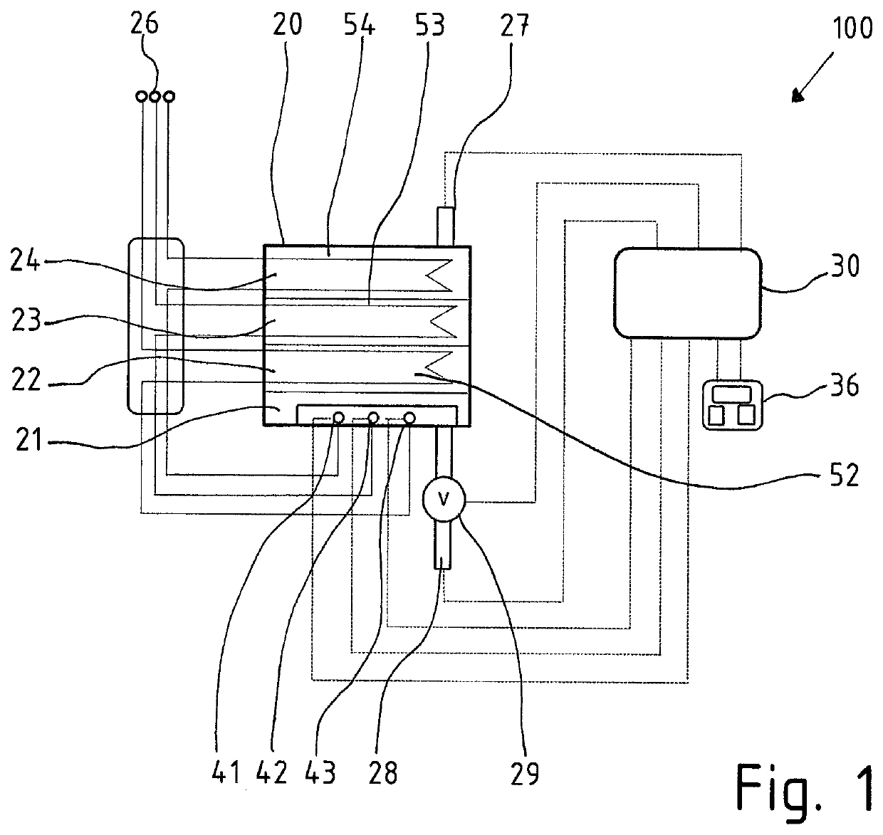
[0044]With reference to the drawings wherein like numerals designate like or corresponding elements throughout the several views, it will be seen that the invention relates to a tankless water heater system 100 as illustrated in the schematic in FIG. 1.
[0045]The basic components of the tankless water heater system 100 are a heat exchanger device 20 and a controller device 30. These components may be physically integrated in a common housing, but the exchanger device 20 can also be operated by the controller device 30 arranged in a remote location wherein the heat exchanger device 20 and the controller device 30 are linked by wires and / or by wireless connections.
[0046]In the illustrated embodiment of the invention the heat exchanger device 20 is built from a sequence of stainless-steel heating tubes 21, 22, 23, 24 welded together, where the water runs through openings in the beginning and the end of each tube thereby constituting a meandering water flow path between inlet opening at ...
PUM
 Abstract
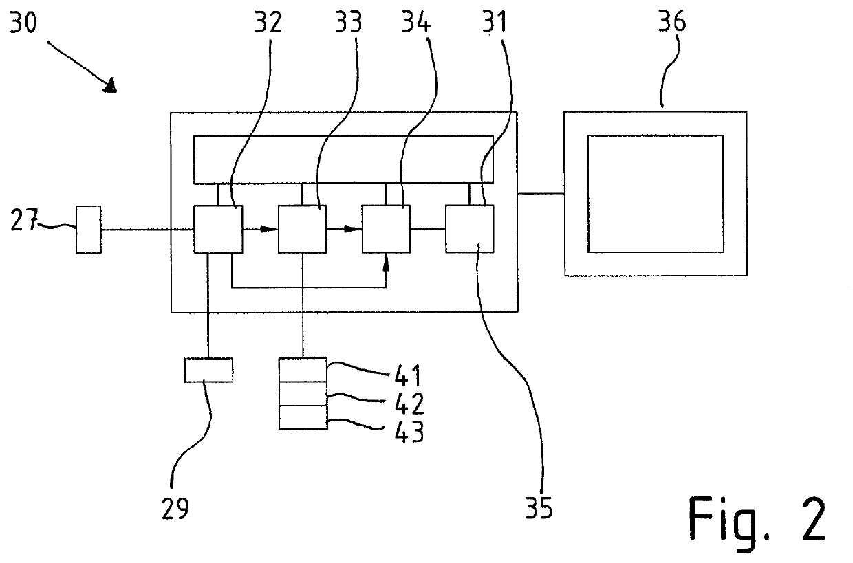
- a controller device (30) with a temperature control unit (35), a tap event counter unit (32), a down-time counter unit (33) and a time delay unit (34);
- an electrical switching element (41, 42, 43) for connecting or disconnecting one or several heating elements (52, 53, 54) to/from a power supply;
- an outlet temperature sensor (27) linked with the temperature control unit (35);
- a flow rate sensor (29);
- wherein:
- the tap counter unit (32) is connected to the flow rate sensor (29) and is triggered when water flow rate exceeds a tap indication threshold {dot over (V)}0
- the down-time counter unit (33) is triggered and retriggered by the tap counter unit (32) and both provide a down-time event signal after any inactivity period with no water flow and records the duration of inactivity;
- the time delay unit (34) is connected to and triggered by the tap counter unit (32) starting a delay period ΔtOFF which duration is switched from a short default delay period to a long delay period by the down-time signal provided by the down-time counter unit (33); and
- the switching elements (41, 42, 53) are triggered by the time delay unit (34) only after the delay period has elapsed.
Description
Claims
Application Information
 - R&D Engineer
- R&D Manager
- IP Professional
- Industry Leading Data Capabilities
- Powerful AI technology
- Patent DNA Extraction
Browse by: Latest US Patents, China's latest patents, Technical Efficacy Thesaurus, Application Domain, Technology Topic.
© 2024 PatSnap. All rights reserved.Legal|Privacy policy|Modern Slavery Act Transparency Statement|Sitemap