Electrical fault detector and method of use

a technology of electrical faults and detectors, applied in the field of detection of electrical faults, can solve problems such as reducing the useful life of electrical conductors, compromising electrical conductors, and many electrical systems suffering from occasional or intermittent electrical faults

Active Publication Date: 2021-01-21
THE BOEING CO
View PDF0 Cites 0 Cited by
  • Summary
  • Abstract
  • Description
  • Claims
  • Application Information

AI Technical Summary

Benefits of technology

This patent describes an electrical system in an aircraft that includes an insulated electrical conductor and an optical fiber installed next to it. The optical fiber has a jacket that can detect an electromagnetic signal generated by an electrical fault on the conductor and alert a processor. The processor can then determine if the electrical fault has occurred and take appropriate action. The technical effect of this system is to provide a means for detecting electrical faults in an aircraft, which can help to improve safety and prevent damage or malfunction.

Problems solved by technology

Many electrical systems may suffer from occasional or intermittent electrical faults, such as electrical arcs or corona discharges where air surrounding an electrical conductor is ionized.
Such electrical faults can compromise electrical conductors by degrading insulation and reducing the useful life of the electrical conductor.
Electrical faults may, in certain circumstances, trigger an overcurrent protection that results in, for example, de-energizing one or more electrical conductors.
However, corona discharges are generally of such low energy that overcurrent protection is not engaged.
Many electrical faults are only revealed, if ever, by a manual visual inspection of the length of the electrical conductor and, even then, it may be difficult to identify the location of, or localize, the electrical fault, for example, the location of an electrical arc or a corona discharge along the length of the electrical conductor.

Method used


Image

  • Electrical fault detector and method of use
  • Electrical fault detector and method of use

Examples


Embodiment Construction

[0010]As used herein, an element or step recited in the singular and preceded by the word “a” or “an” should be understood as not excluding plural elements or steps unless such exclusion is explicitly recited. Furthermore, references to “one embodiment” of the present invention or the “exemplary embodiment” are not intended to be interpreted as excluding the existence of additional embodiments that also incorporate the recited features.

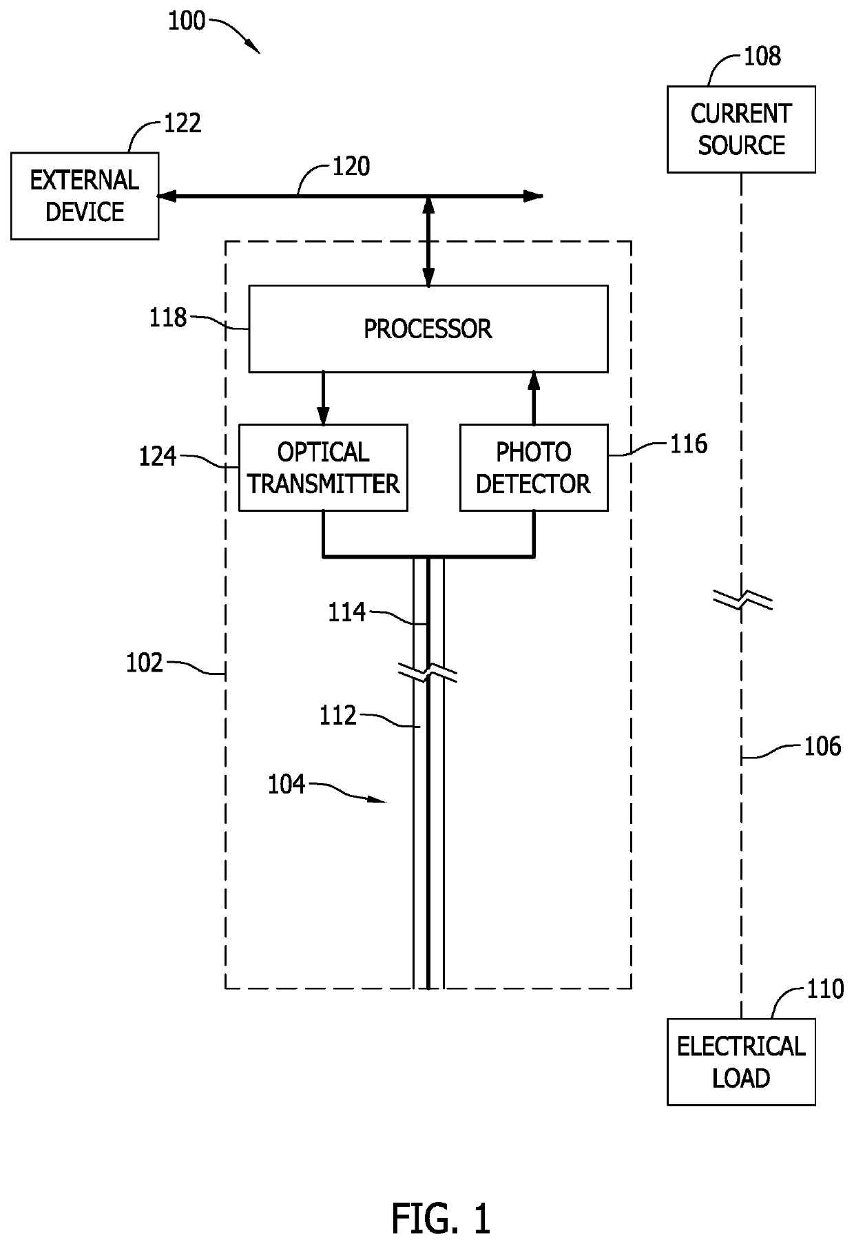
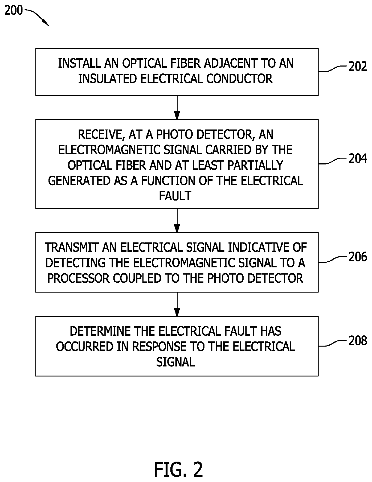
[0011]Embodiments of the electrical fault detectors and methods described herein enable detection of an electrical fault occurring on an electrical conductor installed in, for example, an aircraft. More specifically, the electrical fault detectors described herein provide an optical fiber installed adjacent to, or co-located with, the electrical conductor. Such electrical conductors may include, for example, one or more power feeders coupled to some current source, such as a battery or generator. Generally, the electrical conductors are insulated, or ...


PUM


Abstract

An electrical system is provided. The electrical system includes an insulated electrical conductor installed in an aircraft and configured to conduct a current over a length of the insulated electrical conductor. The electrical system includes an optical fiber includes a jacket surrounding an optical core, the optical fiber installed adjacent to the insulated electrical conductor. The electrical system includes a photo detector coupled to the optical fiber and configured to detect an electromagnetic signal carried by the optical fiber and at least partially generated as a function of an electrical fault that occurs at a point along the length of the insulated electrical conductor.

Description

FIELD[0001]The field of the disclosure relates generally to detection of electrical faults in electrical conductors, and more specifically to an electrical fault detector and a method of use.BACKGROUND[0002]Many electrical systems may suffer from occasional or intermittent electrical faults, such as electrical arcs or corona discharges where air surrounding an electrical conductor is ionized. Such electrical faults can compromise electrical conductors by degrading insulation and reducing the useful life of the electrical conductor. Electrical faults may, in certain circumstances, trigger an overcurrent protection that results in, for example, de-energizing one or more electrical conductors. However, corona discharges are generally of such low energy that overcurrent protection is not engaged. Many electrical faults are only revealed, if ever, by a manual visual inspection of the length of the electrical conductor and, even then, it may be difficult to identify the location of, or lo...

Claims


Application Information

Patent Timeline
IPC IPC(8): G01R31/11G01R31/02G01D5/353G01D5/40
CPCG01R31/11G01D5/40G01D5/35306G01R31/021G01R31/008G01R31/083G01R31/1209G01R31/1218G01R31/58
Inventor SEVERNS, CHRISTOPHER MARKKHOZIKOV, VYACHESLAV
Owner THE BOEING CO
Why Eureka
Try Eureka