
Display device

a display device and display region technology, applied in the field of display devices, can solve the problems of affecting the shooting performance and image quality of the camera, and achieve the effect of improving the visual experience and visual appeal of the display device, and effectively increasing the display region of the display devi

Active Publication Date: 2021-01-21
WUHAN CHINA STAR OPTOELECTRONICS TECH CO LTD
View PDF0 Cites 2 Cited by
  • Summary
  • Abstract
  • Description
  • Claims
  • Application Information

AI Technical Summary

Benefits of technology

The patent text describes a technology that puts the camera module under the display panel, which increases the screen ratio of the display and allows for a more visually appealing design. This results in a narrower bezel or no bezel at all, improving the overall visual experience of the display device.

Problems solved by technology

Since light of the backlight module easily leaks through edges of the via holes of the upper polarizing film and the lower polarizing film, shooting performance and image quality of the camera are affected.

Method used


Image

  • Display device

Examples


Embodiment Construction

[0027]Any embodiment in the following description mean that specific features, structures, or characteristics described in connection with the embodiment may be included in at least one embodiment of the invention. The same terms appearing in different places in the specification are not necessarily limited to the same embodiment, but should be understood as independent or alternative embodiments to other embodiments. In view of the technical solutions disclosed in the embodiments of the present invention, those skilled in the art should understand that the embodiments described herein may have other combinations or modifications in accordance with the embodiments of the present invention.

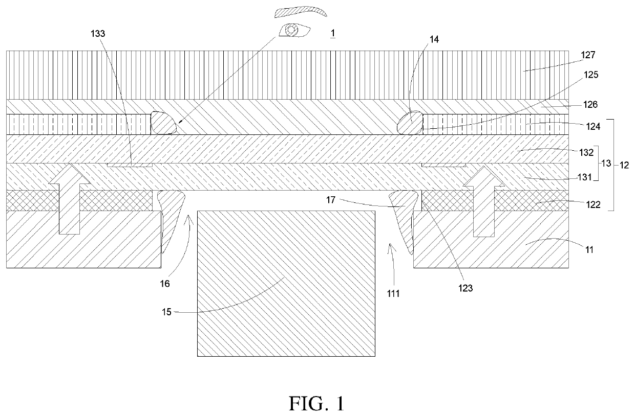
[0028]Please refer to FIG. 1. FIG. 1 is a cross-sectional view illustrating a display device with an under-screen camera according to the present invention. As shown in the drawing, the present invention provides a display device 1 with an under-screen camera. The display device 1 comprises a backl...


PUM

PropertyMeasurementUnit
light shieldingaaaaaaaaaa
sizeaaaaaaaaaa
structuresaaaaaaaaaa

Abstract

A display device is provided, including a backlight module and a liquid crystal display module. The backlight module is provided with a through hole. The liquid crystal display module includes a display panel and a lower polarizing film and an upper polarizing film arranged on two opposite sides of the display panel. A first via hole is in the lower polarizing film. A second via hole is in the upper polarizing film and arranged corresponding to the first via hole. A light shielding portion is arranged at two side edges of the second via hole. Such configuration avoids light leakage from the first via hole and the second via hole of the liquid crystal display module, and improves shooting performance of the camera module and also enhances market competitiveness.

Description

FIELD OF DISCLOSURE[0001]The present invention relates to a field of display devices and in particular, to a display device with an under-screen camera.DESCRIPTION OF RELATED ART[0002]With development of liquid crystal display technology—especially the development of full-screen technology, there has been an increasing demand for a display device (such as a tablet computer and a smart phone) which has an opening in the display region and has an in-plane camera (i.e., an under-screen camera) set therein to increase a screen ratio of the display region. A conventional display device comprises a display panel, a backlight module disposed under the display panel, a glass cover disposed above the display panel, and a camera module disposed under the glass cover. The backlight module is further provided with a camera hole for accommodating the camera module. In addition, upper and lower polarizing films attached to upper and lower surfaces of the display panel are also provided with via h...

Claims


Application Information

Patent Timeline
Patent Type & Authority Applications(United States)
IPC IPC(8): G02F1/1335G02F1/1368
CPCG02F1/133512G02F1/133528G02F2202/28G02F1/133514G02F1/1368G02F1/13338G02F1/1336H04N23/57G02F1/133331G02F1/133325G03B30/00G03B11/045G03B17/02H04N23/53
Inventor ZHANG, PENG
Owner WUHAN CHINA STAR OPTOELECTRONICS TECH CO LTD
Learn More