
Hanging structure and handheld shower

a technology of hanging structure and handheld shower, which is applied in the direction of water installation, spray nozzles, constructions, etc., can solve the problems of high cost and affect the experience of strong magnets, and achieve the effects of simple structure, low cost and quick assembly and quick disassembly

Active Publication Date: 2021-02-25
XIAMEN SOLEX HIGH TECH IND CO LTD
View PDF2 Cites 3 Cited by
  • Summary
  • Abstract
  • Description
  • Claims
  • Application Information

AI Technical Summary

Benefits of technology

The present patent provides a mounting structure for a handheld shower that allows for quick assembly and disassembly with a simple and low-cost design. This mounting structure includes a hanging hook and sleeve with guides for smooth hanging, an opening width-increasing recess for easier mounting, and three guiding processes to ensure smooth coupling of the shower to the hanging seat without shaking. These technical improvements improve the performance and user experience of the mounting process.

Problems solved by technology

The cost of a strong magnet is high and an instantaneous collision between the handheld shower and the hanging seat generates a lot of noise, which affects the experience.

Method used


Image

  • Hanging structure and handheld shower
  • Hanging structure and handheld shower
  • Hanging structure and handheld shower

Examples


embodiment 1

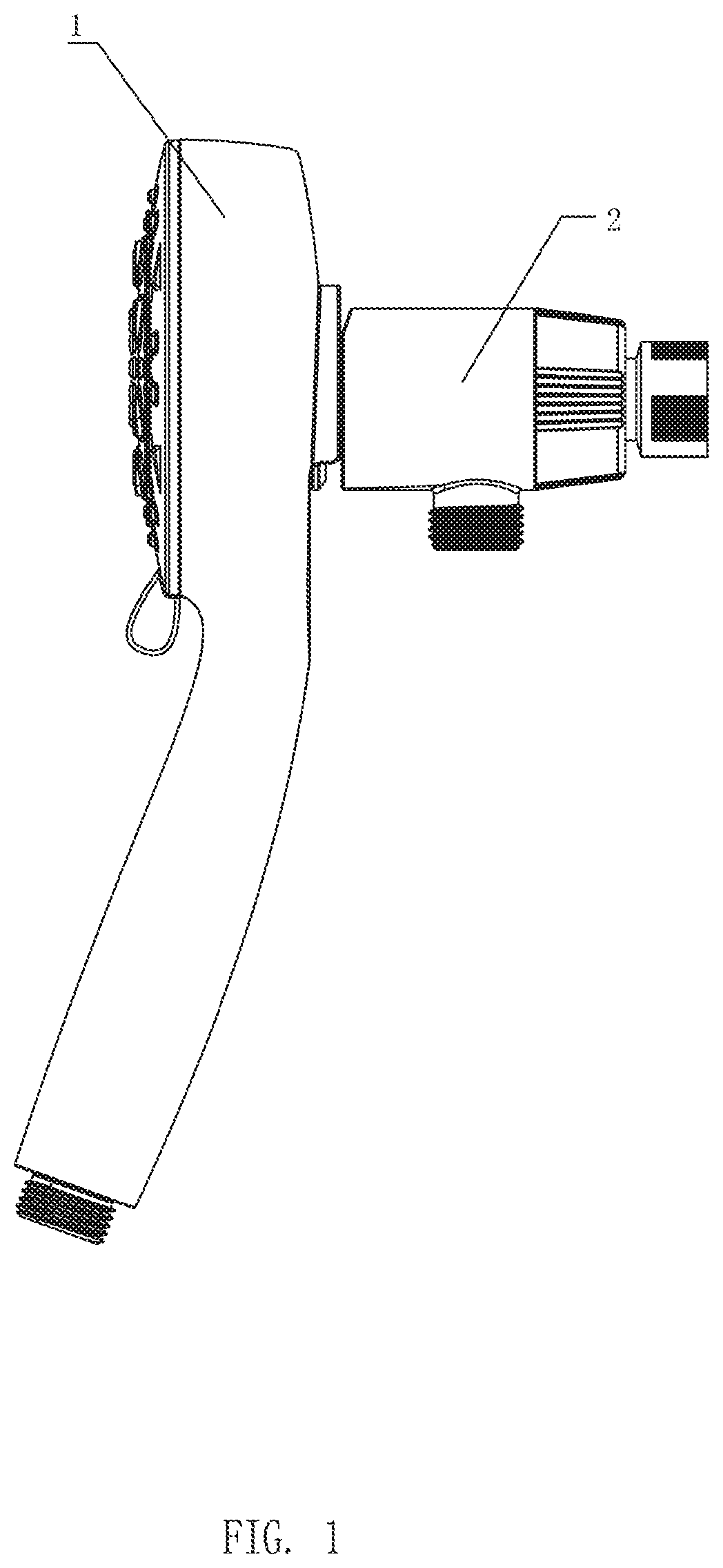
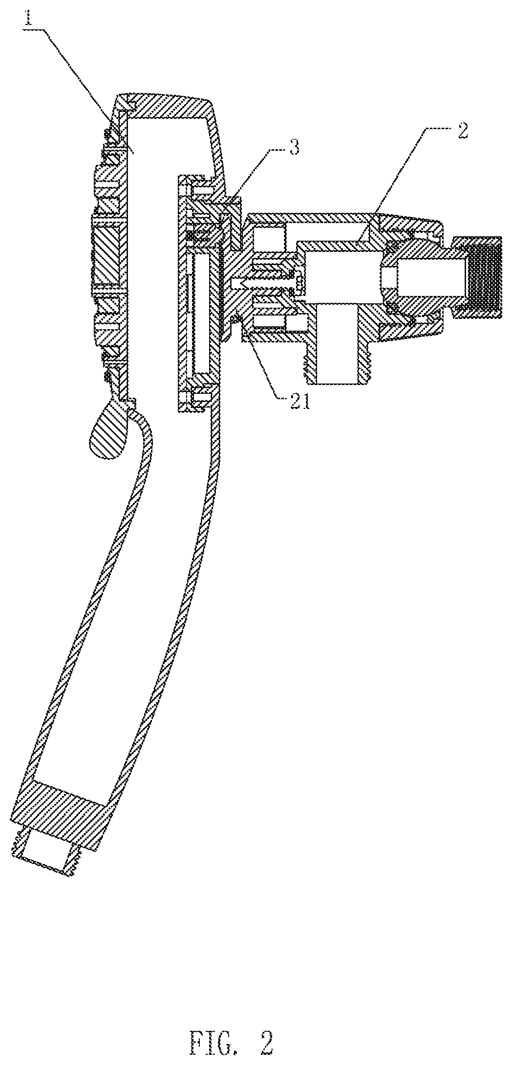
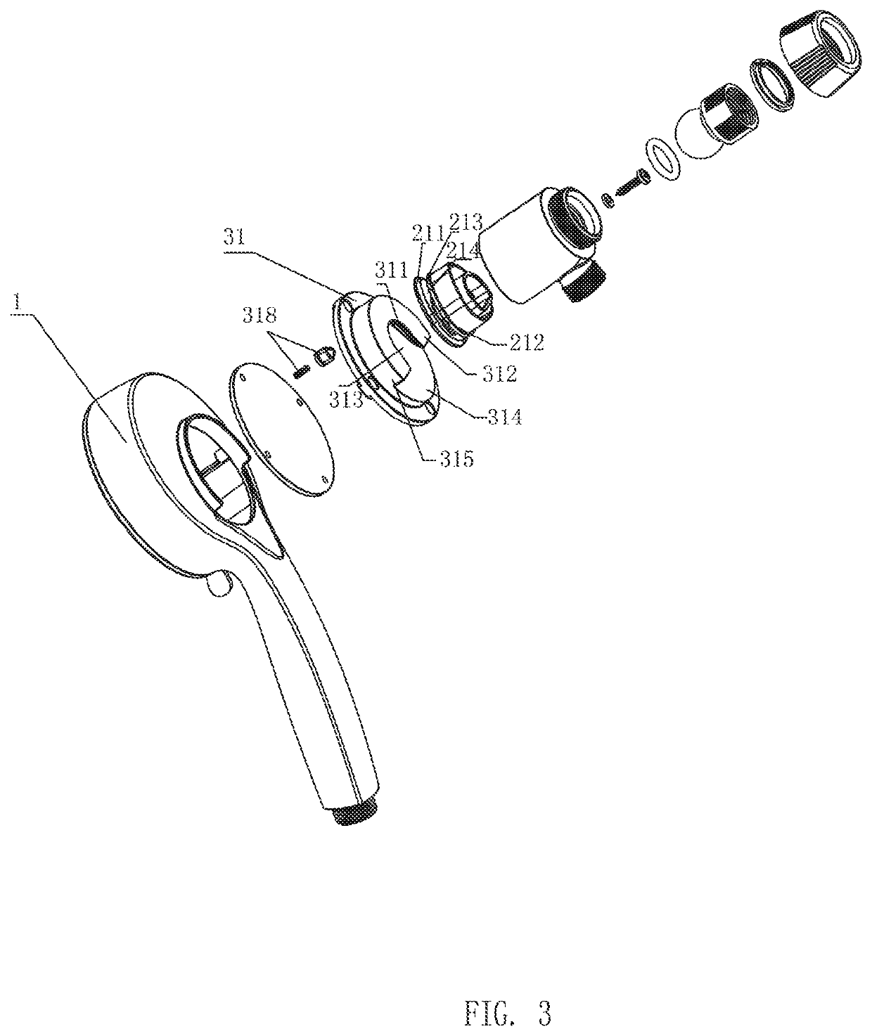
[0036]Referring to FIGS. 1-19, the present disclosure provides a hanging structure of a handheld shower. The hanging structure comprises a handheld shower 1 and a hanging seat 2. The hanging seat 2 is disposed on a wall surface, and a side of the handheld shower 1 facing the hanging seat 2 is disposed with a hanging element 3.

[0037]Opposite sides of the hanging element 3 and the hanging seat 2 respectively comprise a hanging sleeve 31 and a hanging hook 21 so as to define a detachable hanging connection. Positions of the hanging sleeve 31 and the hanging hook 21 are also interchangeable. That is, the hanging sleeve 31 may be disposed on the hanging seat 2, and the hanging hook 21 may be disposed on the hanging element 3. The simple variation of this embodiment is not described herein.

[0038]In some embodiments, the hanging sleeve 31 comprises a receiving cavity 311. A lower portion of the receiving cavity 311 comprises an opening surface 319, and a first side of the receiving cavity ...

embodiment 2

[0057]Referring to FIG. 20, this embodiment differs from Embodiment 1 in that the first portion 211 has a circular shape. Further, the positioning hole 219 is a circular ring. As the positioning hole 219 is a circular ring, the handheld shower 1 can be hung on the hanging seat 2 from any angle.

embodiment 3

[0058]Referring to FIG. 21, this embodiment differs from the Embodiment 1 in that the hanging seat 2 is disposed on a top spray shower 10, so that the handheld shower 1 is hung on the top spray shower 10 to define a combination shower.


PUM


Abstract

A hanging structure comprises a hanging element and a hanging seat. Opposite sides of the hanging element and the hanging seat respectively comprise a hanging sleeve and a hanging hook configured to define a detachable hanging connection. The hanging sleeve comprises a receiving cavity, and a lower portion of the receiving cavity comprises an opening surface. A first side of the receiving cavity facing the hanging hook comprises a baffle board, and a lower end surface of the baffle board comprises an opening extending toward an upper end surface of the baffle board. The hanging hook comprises a first portion configured to be disposed in the receiving cavity and a second portion configured to be disposed in the opening.

Description

RELATED APPLICATIONS[0001]This application claims priority to Chinese patent application number 201921361071.9, filed on Aug. 21, 2019, which is incorporated herein by reference.FIELD OF THE DISCLOSURE[0002]The present disclosure relates to a mounting structure, and more particularly to a hanging structure.BACKGROUND OF THE DISCLOSURE[0003]Successful hanging technology on the market today for showers often use magnetics. By placing strong magnets inside a handheld shower and a hanging seat, or by placing a strong magnet on either the handheld shower or the hanging seat and placing an iron piece on the other of the handheld shower and the hanging seat, the handheld showerhead can be magnetically held in place. The cost of a strong magnet is high and an instantaneous collision between the handheld shower and the hanging seat generates a lot of noise, which affects the experience.BRIEF SUMMARY OF THE DISCLOSURE[0004]The present disclosure provides a mounting structure, which can realiz...

Claims


Application Information

Patent Timeline
IPC IPC(8): B05B15/62E03C1/06
CPCB05B15/62E03C1/06B05B1/18
Inventor ZHUO, ZHIWEICHEN, DONGHAILIN, FENGDE
Owner XIAMEN SOLEX HIGH TECH IND CO LTD
Learn More