Adaptatively morphing surgical grasper

a technology of surgical graspers and adapted morphing, which is applied in the field of mechanical endeffectors, can solve the problems of imposing limitations on workspace and tool operability, unable to achieve effective compromise between the aforementioned opposite needs, and longer deformable tooltips that are intrinsically less effective towards the distal end

Active Publication Date: 2021-03-04
FOND INST ITAL DI TECH
View PDF7 Cites 1 Cited by
  • Summary
  • Abstract
  • Description
  • Claims
  • Application Information

AI Technical Summary

Benefits of technology

[0032]Another advantage of the present invention is that the underlying mechanical action of the miniaturised grasper device, i.e. its adaptive deformation, is intrinsically passive: additional mechanisms, related actuation units or sensors to trigger them are not needed.
[0033]Furthermore, the grasper device according to this invention can advantageously be applied to robotic effectors (e.g. the da Vinci tools, devised for teleoperation) as well as to non-robotic effectors (e.g. “traditional” laparoscopic tools, devised for direct manual operation).
[0034]It will also be appreciated that the design of the proposed grasper affects the tip of the main tool only: there is no need of extra assistant tools (also needing extra incisions). This also promotes tool dexterity: the proposed technical solution can be implemented, e.g., on top of highly articulated robotic effectors.
[0035]Moreover, the proposed tooltip morphing principle and structure can be integrated into generic manipulators: hence, it could be extended to those application fields wherein a grasping action which is both safe for the object and effective / reliable for the operator is sought, including handling of fragile / valuable materials, such as for example glass or food.

Problems solved by technology

However, the prior art does not provide an effective compromise between the aforementioned opposite needs.
However, jaw deformation along the longitudinal direction entails an increase of the tooltip length, thus posing limitation on the workspace and tool operability.
Moreover, longer deformable tooltips are intrinsically less effective towards their distal end because of basic mechanical effects.
Also in this case, the tool does not allow an optimal and firm retaining of the grasped tissue.

Method used


Image

  • Adaptatively morphing surgical grasper
  • Adaptatively morphing surgical grasper
  • Adaptatively morphing surgical grasper

Examples


Embodiment Construction

[0062]In the following, several embodiments of the invention will be described. It is intended that the features of the various embodiments can be combined, where compatible. In general, subsequent embodiments will be disclosed only with respect to the differences with the previously-described ones.

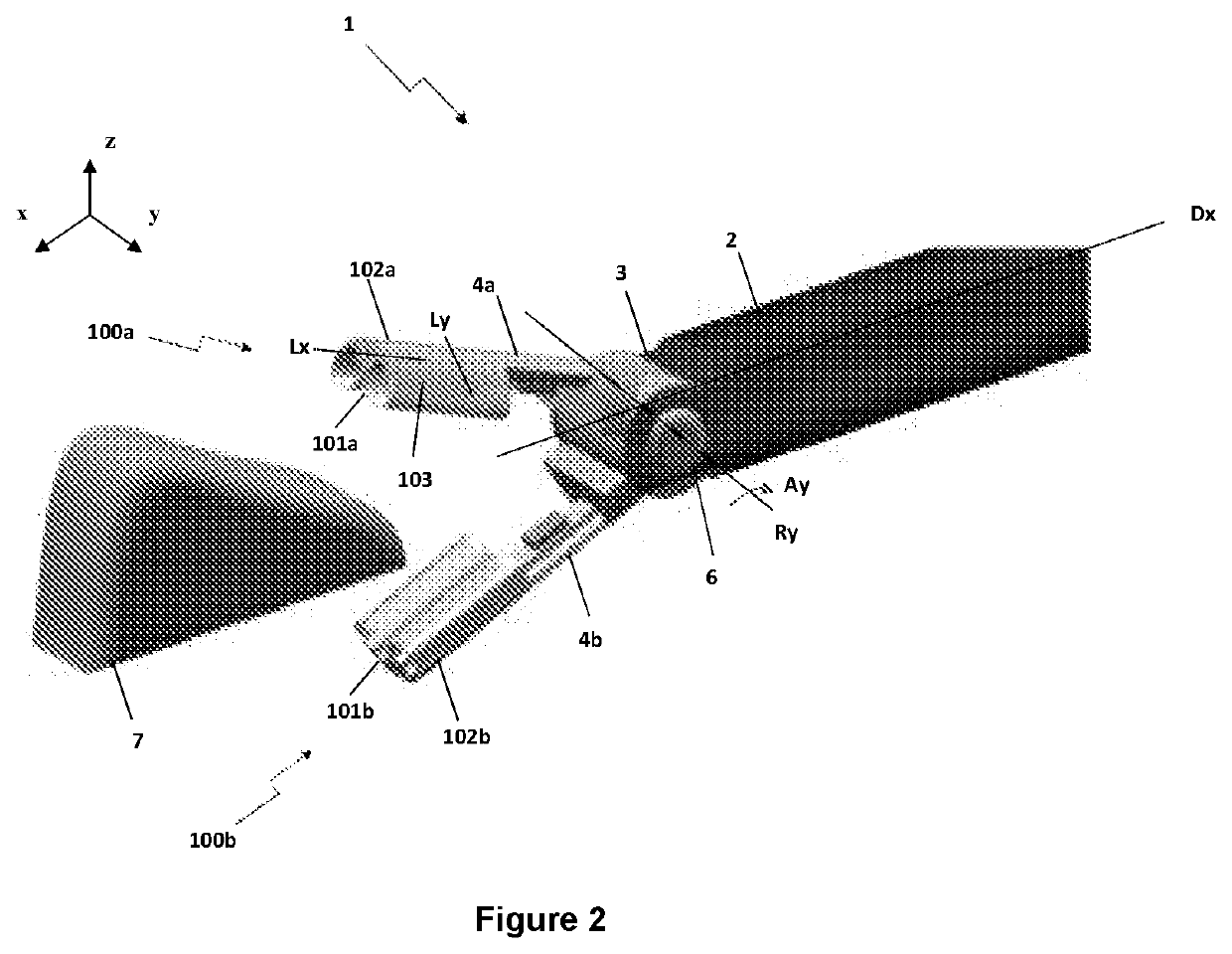
[0063]With reference to FIG. 2, a grasper device, or grasper, according to a preferred exemplary embodiment of the invention is globally denoted by 1. Grasper 1 is configured to be affixed to a support shaft 2 of a main surgical tool. Grasper device 1 mainly comprises a first jaw 100a and a second jaw 100b, which can have the same structure and configuration and which are rotatably coupled at a joint 6.

[0064]For better clarity, in the following directions will be defined in conjunction with reference systems (x, y, z) fixed with device jaws 100a, 100b. In FIG. 2, one of such system is represented schematically.

[0065]Shaft 2 develops along a main longitudinal direction Dx, which is represe...


PUM


Abstract

A grasper device for mini-invasive surgery procedures is provided, having two jaws, each of which having two elastically-deformable elements fixed one another and developing according to a main longitudinal direction, in particular a front element which contacts the tissue to be grasped and a back support element receiving a grasping force from a proximal command and having a higher modulus of elasticity than the front element. During the application of a grasping force Fz, the two elements deform along a transverse direction that is orthogonal to the main longitudinal direction and to the grasping force Fz.

Description

TECHNICAL FIELD[0001]The present invention relates to mechanical end-effectors, in particular to a miniaturized grasper or retractor devised to grasp or retract soft tissue during Minimally Invasive Surgery (MIS) procedures.BACKGROUND[0002]Minimally Invasive Surgery (MIS) is a growing field of technology aimed at reducing the negative effects upon patients of traditional open-surgery procedures, such as scars, infections, patient discomfort and long recovery times.[0003]Known techniques of MIS employ tools, which may be manually or robotically controlled, to manipulate tissues. Typically, MIS procedures are carried out by inserting, through an already existing orifice or through incisions having dimensions ranging from few millimetres to centimetres, a tethered tool into the surgical site of interest. MIS tools are similar to those employed in conventional open-surgery, except that their end-effectors, i.e. the working extremities, are connected to a handle by means of a surgical su...

Claims


Application Information

Patent Timeline
Patent Type & Authority Applications(United States)
IPC IPC(8): A61B17/29
CPCA61B17/29A61B2017/00876A61B2017/2945A61B2017/2825A61B2017/2926
Inventor SINIBALDI, EDOARDOHUAN, YUMENCIASSI, ARIANNAMAZZOLAI, BARBARA
Owner FOND INST ITAL DI TECH
Why Eureka
Try Eureka