Spray Gun

a spray gun and spray technology, applied in the field of spray guns, can solve the problems of affecting the normal operation of the spray gun, operating efficiency, and lowering the painting efficiency, so as to reduce the difficulty in manufacturing the pump, reduce the difficulty of pressure, and simplify the pump structure

Inactive Publication Date: 2021-03-04
ZHEJIANG PRULDE ELECTRIC APPLIANCE CO LTD
View PDF2 Cites 0 Cited by
  • Summary
  • Abstract
  • Description
  • Claims
  • Application Information

AI Technical Summary

Benefits of technology

[0021]5. The air outlet passage and the venting passage are arranged in a “┌” shape. The detoured venting path guarantees smooth venting of the air while preventing the liquid from leaking out of the venting port.
[0022]6. A relief valve port in communication with the spray chamber is provided on the pump. The air outlet passage communicates with the relief valve port. A pressure relief assembly is provided at the relief valve port. With such configurations, the pressure inside the cup is relieved via the air outlet passage. As such, the air outlet passage further functions to relieve pressure. In other words, the air outlet passage has dual functions, saving one passage, thereby simplifying the structure of the pump and lowering the difficulty in manufacturing the pump.
[0023]7. The pump is provided with a charging port in communication with the cup. A charging screw-plug extending into the cup is connected with the charging port, and a filter mesh assembly is connected at a lower end of the screw-plug. Such configurations facilitate the liquid in the flexible cup to enter the spray chamber. Besides, the filter mesh assembly enables filtering of the liquid so as to guarantee a finer and homogeneous spraying of the liquid.
[0024]8. The filter mesh assembly comprises a filter cover and a filter disc. The filter cover is provided with a filter port, and the filter disc is provided in the filter port. The filter mesh assembly of this structure not only facilitates the liquid to enter the charging screw-plug to guarantee liquid charging effect, but also guarantees liquid filtering effect. Besides, the simple structure is easy to manufacture and mold.
[0025]9. A surrounding barrier surrounding the filter disc is provided on the filter cover to prevent the flexible cup body that is squeezed from attaching to the filter disc. With such configurations, the flexible cup body becomes gradually deflated during continuous painting, while the surrounding barrier prevents the deflated flexible cup body from attaching to the filter disc and thus prevents blocking the liquid from entering the screw-plug. As such, normal liquid charging is guaranteed, and the liquid is able to be completely sprayed out, avoiding liquid waste.
[0026]10. A plurality of notches are provided on the surrounding barrier to partition the surrounding barrier into a plurality of stop blocks. This configuration not only saves the manufacturing material of the surrounding barrier and thus reduces the manufacturing cost, but also prevents the deflated flexible cup body from attaching to the filter disc, thereby guaranteeing a normal liquid charging and then guaranteeing painting effect.

Problems solved by technology

However, this structure still has a problem, i.e., when air is present in the liquid container, the liquid cannot rise up into the spray chamber of the pump to implement spray coating, which affects normal operation of the spray gun and lowers painting efficiency and operating efficiency.

Method used


Image

  • Spray Gun
  • Spray Gun
  • Spray Gun

Examples


Embodiment Construction

[0036]Hereinafter, the present disclosure will be described in further detail through embodiments with reference to the accompanying drawings. It needs to be understood that the oriental or positional relationships indicated by the terms “upper,”“lower,”“left,”“right,”“longitudinal,”“transverse,”“inner,”“outer,”“vertical,”“horizontal,”“top,”“bottom,” etc. are only based on the drawings, intended only for facilitating or simplifying illustration of the present disclosure, not for indicating or implying that the devices / elements have to possess such specific orientations or have to be configured and operated with such specific orientations. Therefore, they should not be understood as limitations to the present disclosure.

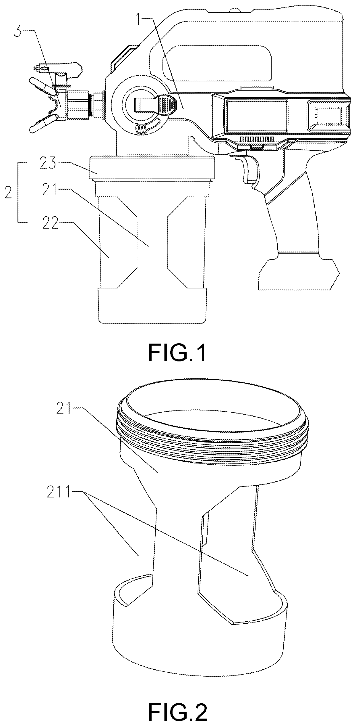
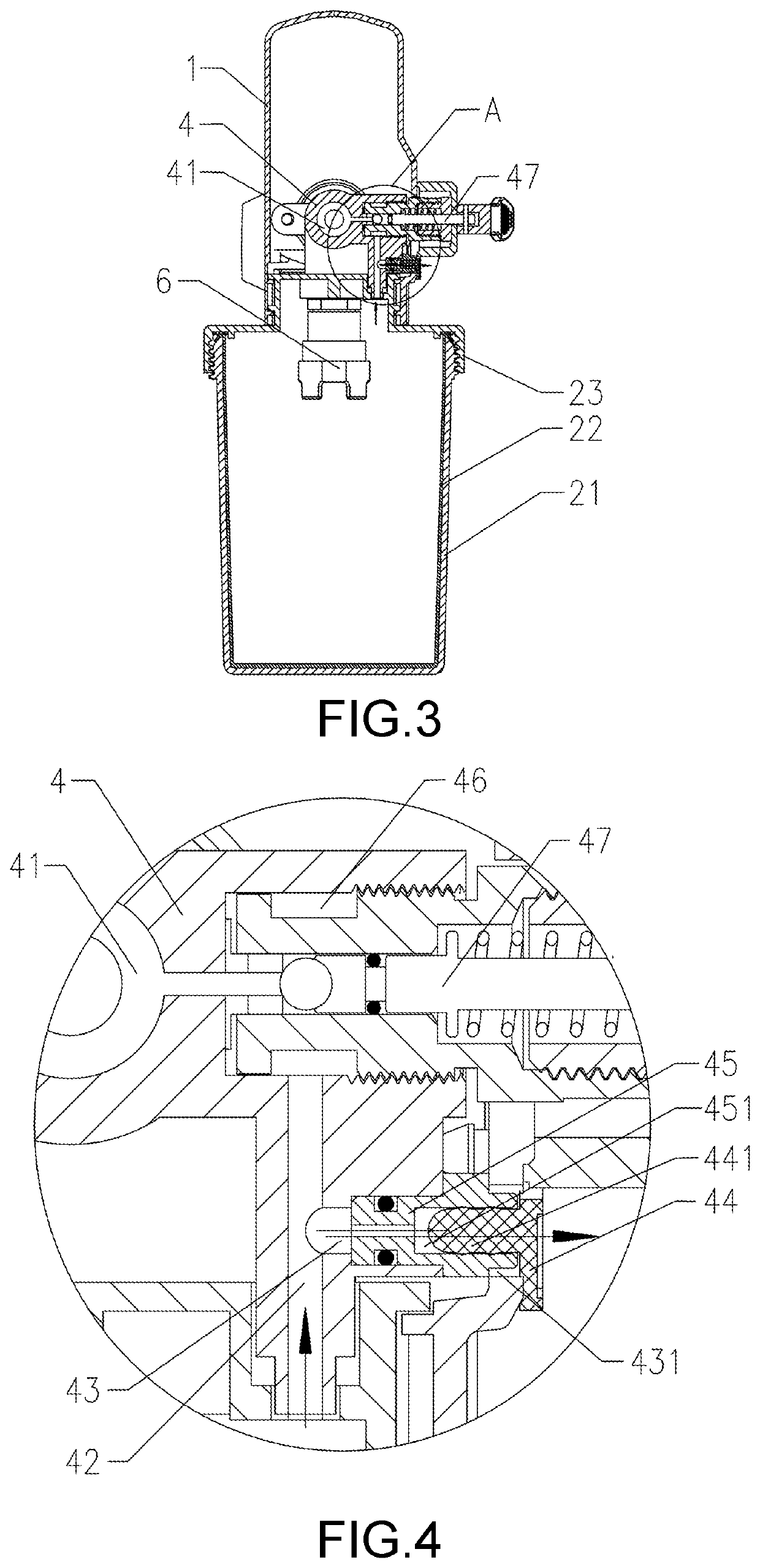
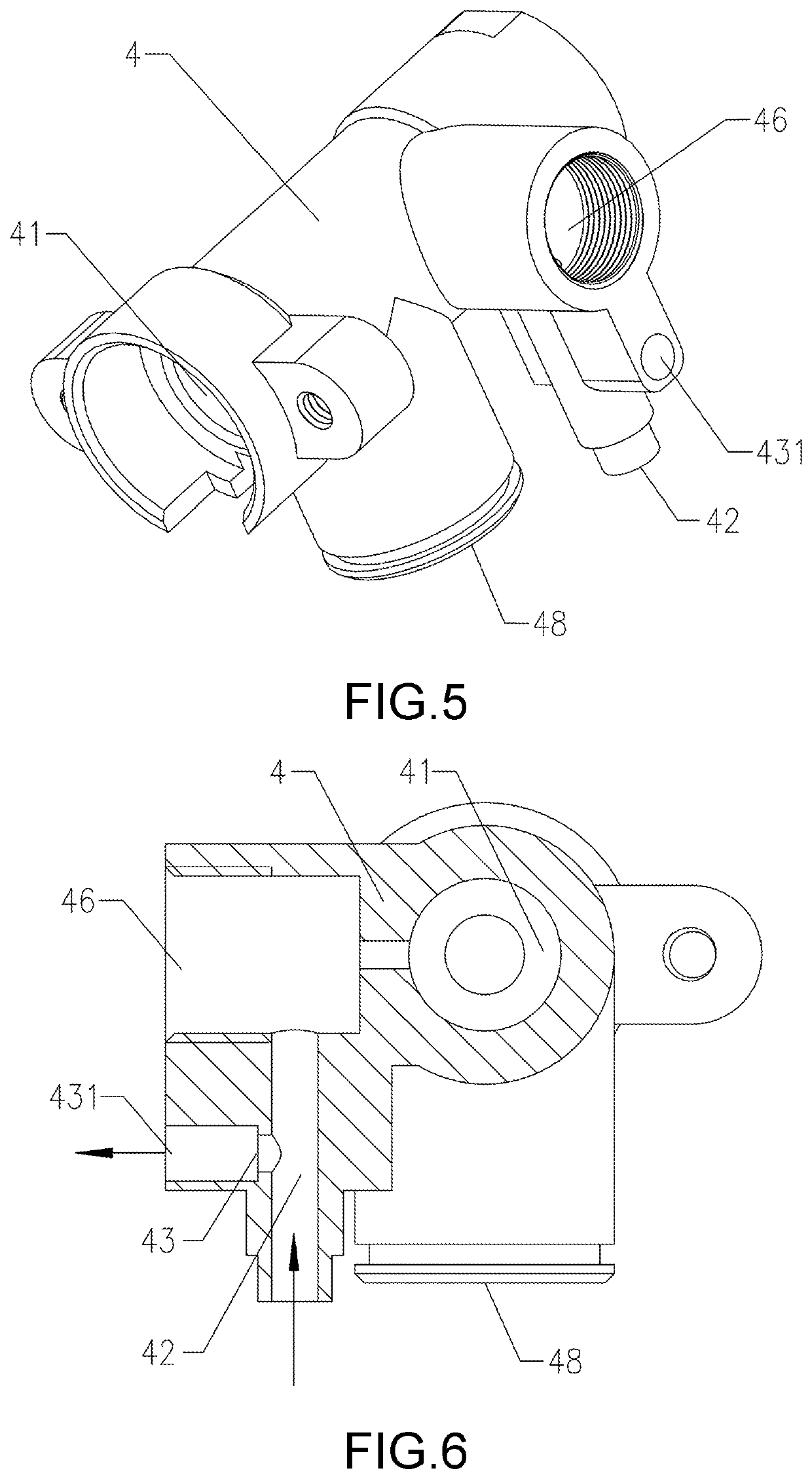
[0037]As shown in FIG. 1 to FIG. 8, embodiments of the present disclosure provide a spray gun which includes a casing 1, a cup 2, a spray nozzle 3 and a pump 4. The pump 4 is provided in the casing 1 and has a spray chamber 41 in communication with the cup 2. The cup ...


PUM


Abstract

A spray gun includes a casing, a cup, a spray nozzle, and a pump. The pump is provided in the casing and has a spray chamber in communication with the cup. The cup includes a cup housing and a flexible cup body provided in the cup housing. A venting structure communicating the cup with an outer environment is provided on the pump. The cup housing is provided with a hollow portion, such that the flexible cup body is manually squeezable to expel air inside the flexible cup body out via the venting structure.

Description

CROSS-REFERENCE TO RELATED APPLICATION[0001]This application claims the priority benefit of China application serial no. 201910813887.9, filed on Aug. 30, 2019. The entirety of the above-mentioned patent application is hereby incorporated by reference herein and made a part of this specification.BACKGROUNDTechnical Field[0002]The present disclosure relates to spray guns, and more particularly relate to a spray gun with efficient painting.Description of Related Art[0003]As an apparatus for atomizing coating, spray guns mainly serve to finish an object to be painted, thereby achieving an aesthetic, smooth and uniform coating. The spray guns mainly leverage the pressure inside a piston to reduce the space in a liquid container, and the increased air pressure forces out the liquid in the liquid container. As the motorized piston moves continuously, the pressure in the spray chamber rises expeditiously, thereby facilitating atomization of the liquid ejected out of the spray nozzle, and i...

Claims


Application Information

Patent Timeline
Patent Type & Authority Applications(United States)
IPC IPC(8): B05B7/24
CPCB05B7/2481B05B7/244B05B7/2408B05B9/0403B05B9/047B05B15/40B05B15/00B05B12/36G06Q10/083G06Q30/0284B05B9/0861
Inventor YANG, WEIMINGHAN, TING
Owner ZHEJIANG PRULDE ELECTRIC APPLIANCE CO LTD
Why Eureka
Try Eureka