Supercharge Your Innovation With Domain-Expert AI Agents!

Printing Apparatus and Printing Method

a printing apparatus and printing method technology, applied in the field of printing apparatuses, can solve problems such as increasing manufacturing costs

Active Publication Date: 2021-03-04
BROTHER KOGYO KK
View PDF0 Cites 1 Cited by
  • Summary
  • Abstract
  • Description
  • Claims
  • Application Information

AI Technical Summary

Benefits of technology

The technical effect of this patent is to reduce a density difference at a boundary between groups of nozzles in an ink-jet printing apparatus without adjusting the output voltage value of a power supply circuit. This is achieved by mixing nozzles from different power supply circuits in the nozzle array, which results in a less significant difference in density between the groups.

Problems solved by technology

Making the output voltage value of the power supply circuit adjustable increases manufacturing cost.

Method used


Image

  • Printing Apparatus and Printing Method
  • Printing Apparatus and Printing Method
  • Printing Apparatus and Printing Method

Examples


Embodiment Construction

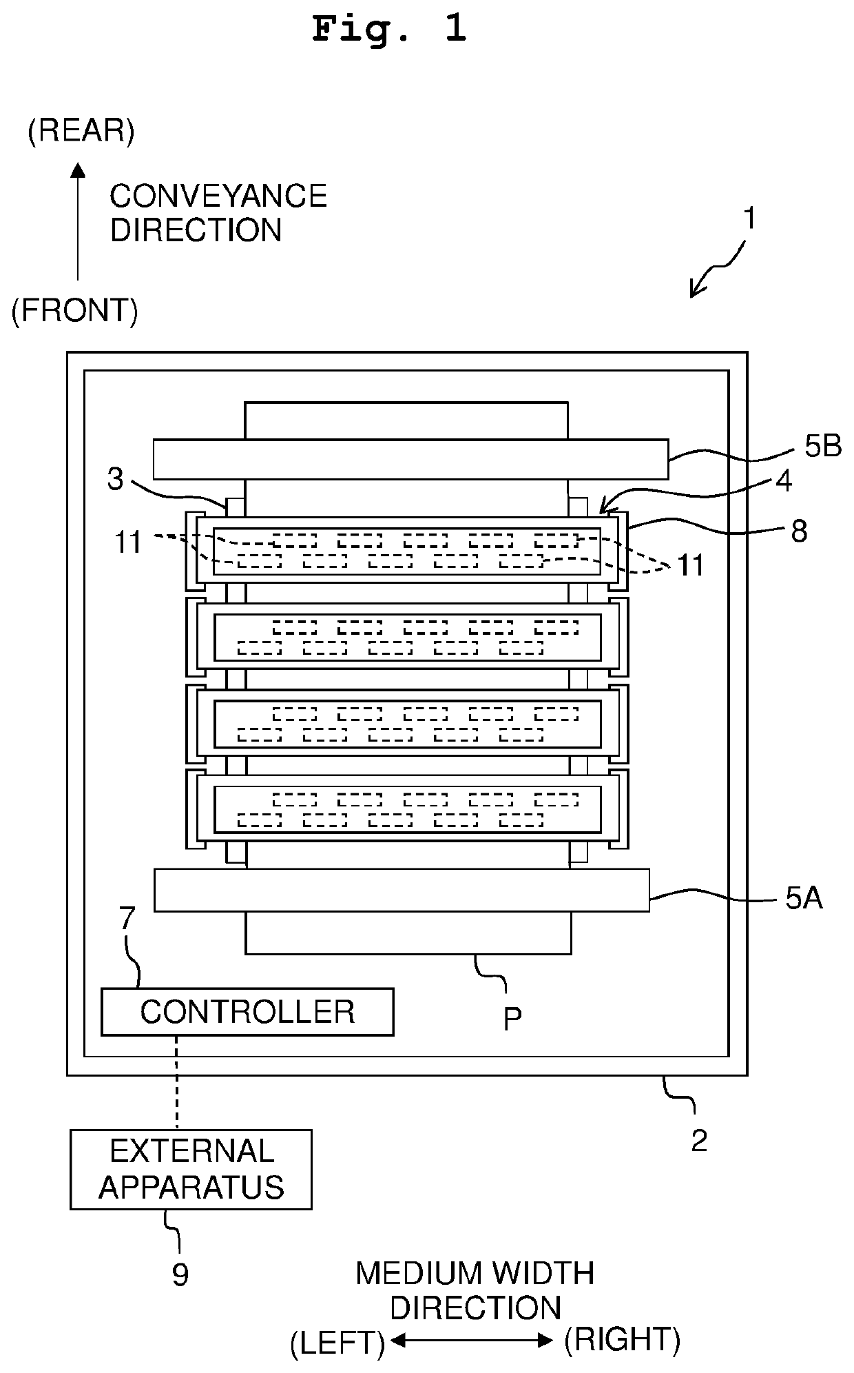
[0026]Referring to FIGS. 1 to 9, a printing apparatus according to an embodiment of the present disclosure is explained below.

[0027]In FIG. 1, an upstream side in a conveyance direction of a sheet-like medium P (for example, paper, cloth, etc.) is defined as a front side of a printing apparatus 1, and a downstream side in the conveyance direction of the medium P is defined as a rear side of the printing apparatus 1. A direction parallel to a surface on which the medium P is conveyed (a surface parallel to a paper surface of FIG. 1) and orthogonal to the conveyance direction is defined as a medium width direction. A left side in FIG. 1 is a left side of the printing apparatus 1, and a right side in FIG. 1 is a right side of the printing apparatus 1. A direction perpendicular to the surface on which the medium P is conveyed (a direction perpendicular to the paper surface of FIG. 1) is defined as an up-down direction of the printing apparatus 1. A front surface of FIG. 1 is an upper si...


PUM


Abstract

A printing apparatus includes: power supply circuits including at least first and second power supply circuits; a head including nozzles, the nozzles forming groups arranged in a first direction, each of the groups including nozzle arrays arranged in the first direction, each of the nozzle arrays extending in a second direction intersecting with the first direction, each of the nozzles being associated with any of the power supply circuits; and a memory storing information. The information indicates correspondence relationships between the nozzles and the power supply circuits, between the nozzles and the groups, and between the nozzles and the nozzle arrays. Printing is performed by driving the head based on the information. The groups include a first group and a second group adjacent to each other in the first direction. The first group includes a first nozzle array adjacent to the second group in the first direction.

Description

CROSS REFERENCE TO RELATED APPLICATION[0001]The present application claims priority from Japanese Patent Application No. 2019-161540 filed on Sep. 4, 2019, the disclosure of which is incorporated herein by reference in its entirety.BACKGROUNDField of the Invention[0002]The present disclosure relates to a printing apparatus configured to discharge ink from nozzles and a printing method.Description of the Related Art[0003]There is known an ink-jet head driving apparatus including: actuators provided for respective nozzles and configured to discharge ink from the nozzles by an amount corresponding to a driving signal; a storage or memory configured to store correction data by which the ink discharge amounts from the respective nozzles are leveled; a selecting section configured to select one driving signal from among driving signals based on the correction data; and a driving section configured to output the selected driving signal to the actuators. In this ink-jet head driving apparat...

Claims


Application Information

Patent Timeline
IPC IPC(8): B41J2/155
CPCB41J2/155B41J2/14201B41J2/04508B41J2/04548B41J2/04586B41J2202/21B41J2/2103B41J2002/14491B41J2202/17
Inventor INOUE, HARUSUGAHARA, HIROTONAGANO, TAROKATO, DAIKI
Owner BROTHER KOGYO KK
Features
  • R&D
  • Intellectual Property
  • Life Sciences
  • Materials
  • Tech Scout
  • Unparalleled Data Quality
  • Higher Quality Content
  • 60% Fewer Hallucinations
Learn More