Inkjet printing apparatus
- Summary
- Abstract
- Description
- Claims
- Application Information
AI Technical Summary
Benefits of technology
Problems solved by technology
Method used
Image

Examples
first embodiment
[0033]A first embodiment of the present invention is described below with reference to the drawings.
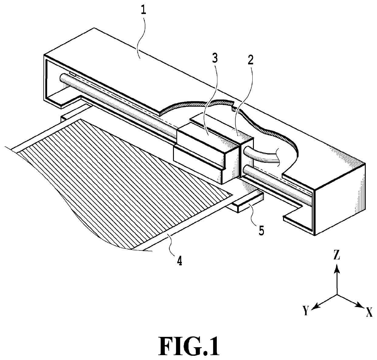
[0034]FIG. 1 is a schematic perspective view illustrating an inkjet printing apparatus (hereafter, also simply referred to as printing apparatus) 1 in the embodiment. The printing apparatus 1 includes a carriage 2 that is provided to be capable of reciprocating in a scanning direction (X direction) intersecting a conveyance direction (Y direction) of a print medium 4 and a print head 3 that is mounted in the carriage 2 and that is capable of ejecting ink drops. The print head 3 performs printing by ejecting the ink drops to the print medium 4 while reciprocating together with the carriage 2 in the scanning direction (X direction). The printing apparatus 1 also includes a platen 5 that supports a back surface of the print medium 4 in the printing.
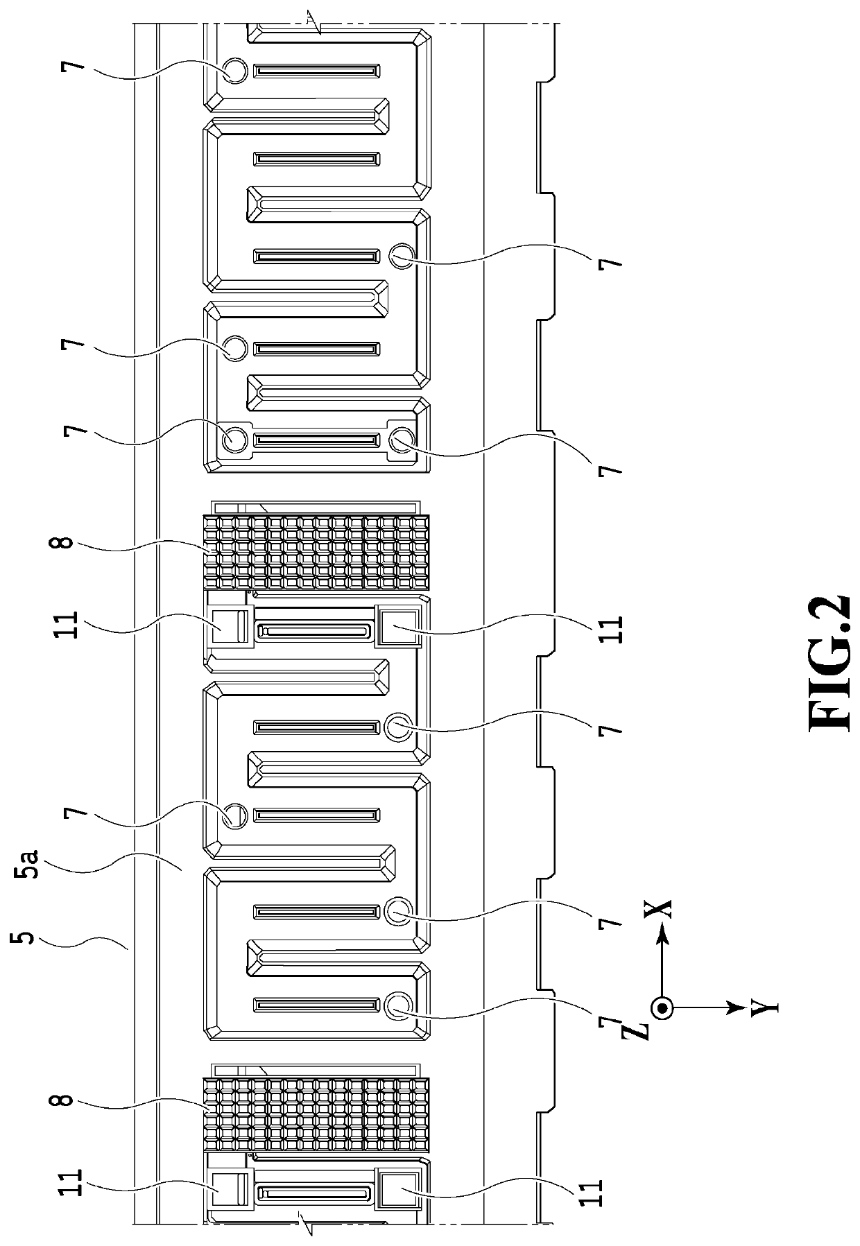
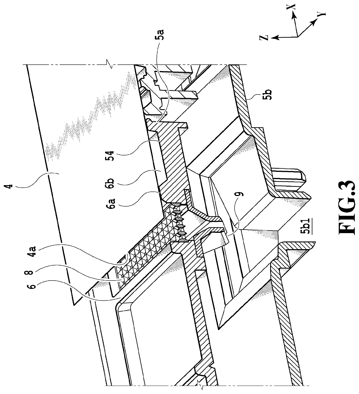
[0035]FIG. 2 is a plan view illustrating the platen 5 and FIG. 3 is a cross-sectional perspective view of the platen 5. The platen 5 extends ...
second embodiment
[0058]A second embodiment of the present invention is described below with reference to the drawings. Since the basic configuration of this embodiment is the same as that of the first embodiment, only the characteristic configurations are described below.
[0059]Conventionally, a method in which dye ink is used on microporous media have been mainly used to print images such as sliver halide photographs from viewpoints of glossiness and the like. However, there is also provided an inkjet printing apparatus that achieves high glossiness while using pigment ink in addition to dye ink from a viewpoint of image fastness.
[0060]In the case where a dot diameter of the pigment ink landing on the print medium is compared with that of the dye ink, the dot diameter of the pigment ink is smaller than the dot diameter of the dye ink and is about 0.75 to 0.8 times the dot diameter of the dye ink. This means that, in the case where the pigment ink and the dye ink land on the same print medium surface...
third embodiment
[0065]A third embodiment of the present invention is described below with reference to the drawings. Since the basic configuration of this embodiment is the same as that of the first embodiment, only the characteristic configurations are described below.
[0066]In the embodiment, in an inkjet printing apparatus that ejects the pigment ink, the surfaces of the ink receiving portion 8 and the ink flow portion 20 are modified to water-repellent surfaces that are surfaces with low wettability.
[0067]FIG. 10 is a cross-sectional view illustrating the ink receiving portion 8 and the ink flow portion 20 in the embodiment. The surfaces of the ink receiving portion 8 and the ink flow portion 20 of the embodiment are modified to water repellent surfaces. Modifying the surfaces of the ink receiving portion 8 and the ink flow portion 20 to water repellent surfaces that are surfaces with low wettability as described above further reduces the wettability and spreadability of the pigment ink that ori...
PUM
 Abstract
Description
Claims
Application Information
 - R&D
- Intellectual Property
- Life Sciences
- Materials
- Tech Scout
- Unparalleled Data Quality
- Higher Quality Content
- 60% Fewer Hallucinations
Browse by: Latest US Patents, China's latest patents, Technical Efficacy Thesaurus, Application Domain, Technology Topic, Popular Technical Reports.
© 2025 PatSnap. All rights reserved.Legal|Privacy policy|Modern Slavery Act Transparency Statement|Sitemap|About US| Contact US: help@patsnap.com