Derailing device

a technology of derailing device and vehicle, which is applied in the direction of devices secured to tracks, railway components, transportation and packaging, etc., can solve the problems of limited vehicle speed, monetary loss, and the design of previous derailing devices, and achieve the effect of maintaining portability, cargo transportation or other efficiency gains

Active Publication Date: 2021-03-04
WESTINGHOUSE AIR BRAKE TECH CORP
View PDF0 Cites 2 Cited by
  • Summary
  • Abstract
  • Description
  • Claims
  • Application Information

AI Technical Summary

Benefits of technology

[0003]In one example, a device includes a first derail block and at least three clamping mechanisms. The first derail block extends from a base and includes a wheel deflecting surface. The wheel deflecting surface is arranged at an angle with regard to a longitudinal axis of a track and is configured to deflect a wheel of a vehicle away from and off the track. The angle is less than or equal to about 13 degrees. The at least three clamping mechanisms are positioned along the derail block and configured to engage with a rail of the track. In this way, a sufficiently shallow angle may be used to increase the maximum speed at which the device can successfully derail a vehicle of various sizes, while the at least three clamping mechanisms along the block enable the forces to be sufficiently dispersed as the vehicle begins impacting the angled derail block and while its forward momentum propels the vehicle forward and thus sideways.
[0004]In another example, a device includes a derail block extending from a base and configured to deflect a wheel of a vehicle off of a track. The block may be directional or bi-directional. To accomplish the wheel deflection the derail block includes a wheel deflecting surface arranged at an angle with regard to a longitudinal axis of the track. The angle is less than or equal to about 13 degrees and a length of the device is greater than or equal to about 53 centimeters (cm) (21 inches (in)). In this way, the device can derail vehicles traveling at a relatively high speed while maintaining portability. Consequently, vehicles may move around the device's operating environment at faster speeds, if desired, resulting in cargo transport or other efficiency gains.

Problems solved by technology

Previous derailing devices, however, have only been designed to derail vehicles traveling at low speeds, such as speeds less than 16 kilometers per hour (km / h) (approximately 10 miles per hour (mph)).
Therefore, in operating environments where the derailing devices are deployed vehicle speed may be limited.
Monetary losses may stem from the cargo transportation inefficiencies.
Increasing a derailing device's upper threshold speed, for example by increasing the size of the device, may be at odds with maintaining device portability.

Method used


Image

  • Derailing device
  • Derailing device
  • Derailing device

Examples


first embodiment

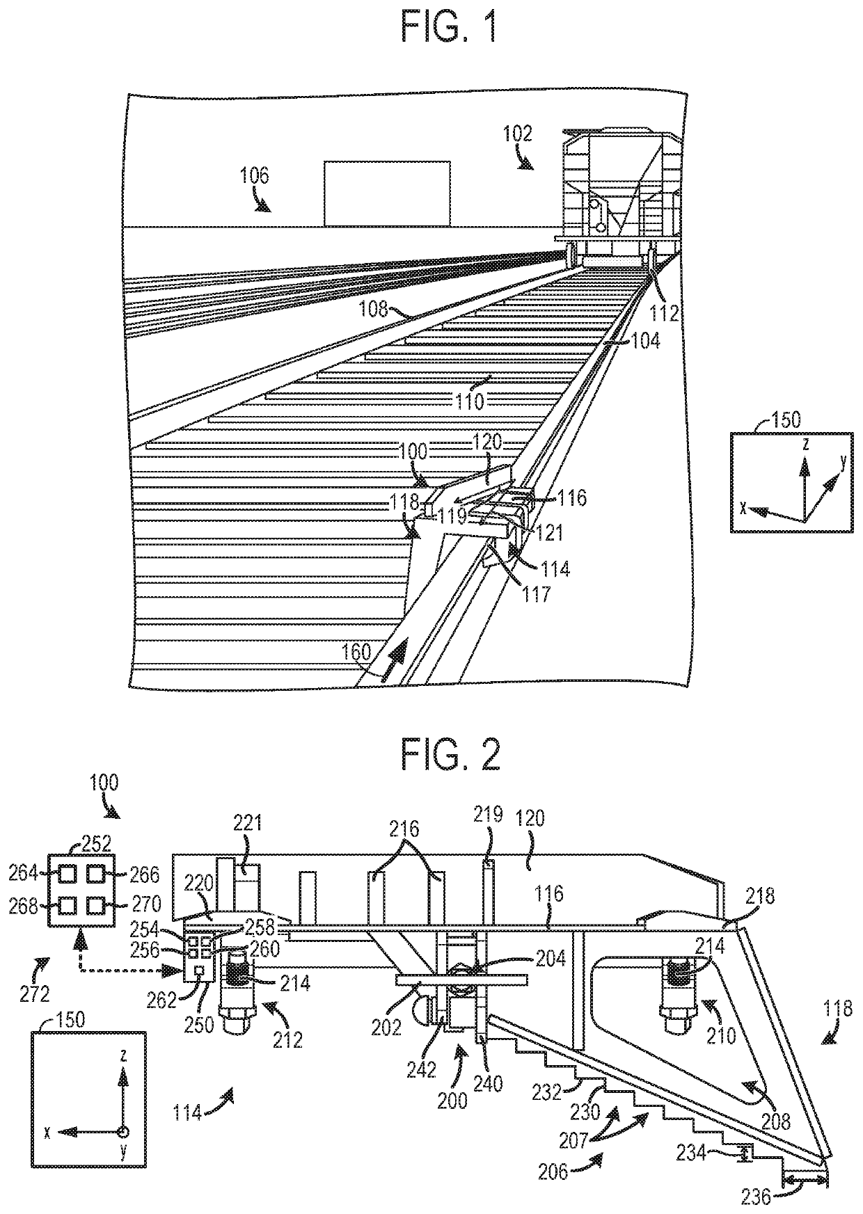
[0037]FIG. 1 illustrates a device 100 configured to derail a vehicle 102 off of a first rail of track 104, when in operation. The vehicle 102 shown in FIG. 1 is a railway vehicle (e.g., rail car, locomotive, handcar, and / or other rail vehicle or combinations thereof). However, the device 100 may be configured to derail vehicles such as on-road vehicles or road-rail vehicles. The locomotive may be freight locomotives (e.g., locomotives generating at least 2982.799 kilowatts (kW) (4000 horsepower (hp)), heavy-haul locomotives generating at least 4474.2 kW (6000 hp), passenger locomotives generating 1491.4 kW (2000 hp) or less, etc.

[0038]The vehicle 102 is located in a railway yard 106, in FIG. 1. However, the device may be deployed in a variety of suitable operating environments such as track junctions, railway stations, rail to ship terminals, etc. As described herein, a track includes a rail or other suitable path along which a wheel of the vehicle 102 travels and interfaces with. A...

third embodiment

[0099]FIG. 27 shows a device 2700. The device 2700 includes a directional derail block 2702 extending from and coupled to a base 2704. However, the directional derail block 2702 shown in FIG. 27 is bi-directional. As such, the directional derail block 2702 functions to derail wheels traveling in a first direction 2706 along a track and a second direction 2708 along the track opposing the first direction. In this way, the device's applicability is increased. However, the bi-directional derail block may increase the weight of the device, thereby decreasing the device's portability.

[0100]To accomplish the bi-directional derailment functionality the derail block 2702 includes a first section 2710 and a second section 2712. However, in another example, the first and second block sections may form a first derail block and a second derail block. In such an example, the first derail block may be disposed adjacent to the second derail block.

[0101]The first section 2710 is arranged at an angl...


PUM


Abstract

Various systems and methods for derailing a vehicle from a track are provided. In one embodiment, a device is provided that includes a directional derail block extending from a base and including a wheel deflecting surface arranged at an angle less than or equal to about 13 degrees with regard to a longitudinal axis of the track and designed to deflect the wheel away from the track. The length of the device is greater than or equal to about 53 centimeters (cm) (21 inches (in)).

Description

BACKGROUND[0001]Vehicle derailing devices are used to guide vehicles off of the tracks on which they are traveling. For example, a derailing device may be placed on tracks adjacent to workers or other personnel, allowing an errant vehicle to be derailed prior to traveling into the person's vicinity. In other situations, vehicle derailing devices may be deployed near railway junctions to prevent inadvertent vehicle travel onto unwanted tracks. Previous derailing devices, however, have only been designed to derail vehicles traveling at low speeds, such as speeds less than 16 kilometers per hour (km / h) (approximately 10 miles per hour (mph)). Therefore, in operating environments where the derailing devices are deployed vehicle speed may be limited. Limiting vehicle speeds decreases the system's efficiency with regard to the movement of cargo (e.g., freight, goods, merchandise, etc.), passengers, etc., through the environment. Monetary losses may stem from the cargo transportation ineff...

Claims


Application Information

Patent Timeline
Patent Type & Authority Applications(United States)
IPC IPC(8): B61K5/06
CPCB61K5/06
Inventor POLLOCK, JARRED MICHAEL
Owner WESTINGHOUSE AIR BRAKE TECH CORP
Why Eureka
Try Eureka