Single-sided electric roller skate

A technology of electric wheels and roller skates, which is applied to roller skates, ice skating, and skateboards. It can solve the problems of poor reliability, complex structure, and low degree of modularization, and achieve the effect of being easy to control and carry.

Inactive Publication Date: 2019-12-31
练新
View PDF0 Cites 0 Cited by
  • Summary
  • Abstract
  • Description
  • Claims
  • Application Information

AI Technical Summary

Problems solved by technology

Existing electric roller skates are worn on two feet separately, and the speed of both feet is coordinated through

Method used


Image

  • Single-sided electric roller skate
  • Single-sided electric roller skate

Examples


Example Embodiment

[0035] Example 1 An electric roller skate with a driving wheel.

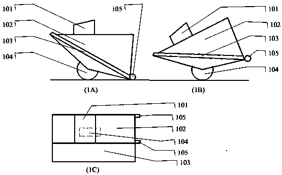
[0036] figure 1 The overall structure of an electric roller skate with a driving wheel provided by the present invention includes a sole body 102, an upper 101, a driving wheel 104, an auxiliary wheel 105, and an additional pedal 103.

[0037] The sole body 102 contains a frame, a power supply and a self-balancing control system, and the frame is used for installation and fixing of other parts. In order to reduce the burden on the feet, part or all of the power supply can also be placed in a bag or backpack carried by the user, and connected to the electric roller skates through contacts or sockets. The power supply includes a power management system.

[0038] A detection device is installed in the shoe body to detect the inclination angle of the shoe body and its change, to judge the user's posture, and the self-balance control system controls the driving wheel speed to complete the speed control and assist the user ...

Example Embodiment

[0051] Example 2 Electric roller skates with two driving wheels.

[0052] It is basically the same as the first embodiment, but with two driving wheels, it is easier for the user to stand and control the turning.

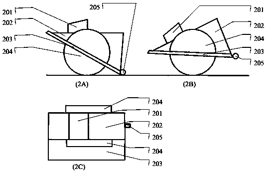
[0053] figure 2 The overall structure of an electric roller skate with a driving wheel provided by the present invention includes a sole body 202, an upper 201, a driving wheel 204, an auxiliary wheel 205, and an additional pedal 203.

[0054] The same parts as in Example 1 will not be repeated. Because there are two driving wheels, only one auxiliary wheel 205 is needed to maintain the stable state of the three wheels on the ground, and the system can control the different speeds of the two driving wheels to realize turning. The detection device is installed in the shoe body to detect the left and right changes of the user's center of gravity or the different back and forth changes of the left and right center of gravity. It can detect different pressures on the left a...


PUM


Abstract

The invention relates to an electric roller skate. The electric roller skate is composed of an electric roller skate main body and an additional pedal, the main body can be worn on one foot or attached to one foot wearing a shoe, and the additional pedal can be used for the other foot to freely step on or leave. A sole is wedge-shaped, the front portion is thin, the rear portion is thick, and thesole is matched with the position of a driving wheel, so that a wedge-shaped upper plane and the ground tend to be parallel when a roller skate heel touches the ground; the additional pedal tends to be parallel to a wedge-shaped lower plane, so that the foot wearing the shoe can tend to stand horizontally when stopping driving, leaning during driving, the heel is higher than the toes, and the footon the additional pedal can tend to stand horizontally while driving. An auxiliary wheel is arranged at the rear end of the heel of the roller skate, and the auxiliary wheel is connected to the shoebody through an elastic mechanism, so that the heel can be reliably on the ground when a person stands on the shoe, and when nobody stands thereon, the auxiliary wheel touches the ground to provide stable support of three wheels touching the ground for the roller skate. A mechanical or electronic mode is adopted to inhibit backward slip of the electric roller skate, and the usability and the safety are enhanced.

Description

technical field [0001] The invention relates to the field of transportation means, in particular to electric roller skates. Background technique [0002] Various sensors are used to detect the attitude of the user and the car, automatically control the speed of the car, and assist the user to achieve balance. The speed and direction can be controlled by the user's attitude, simplifying the structural composition and use requirements of the transportation tool, two-wheel balance car, single-wheel balance Cars, self-balancing scooters, self-balancing twisting cars, etc. are mature and available. However, its portability, safety, and passability are still unsatisfactory. Common insufficient power and obstacles that cannot pass require better portability. Portability requires reducing the wheel diameter, while passability requires larger wheels. Poor passability will cause users to fall and bring safety problems. At this time, a larger wheel diameter means more danger. [0003...

Claims


Application Information

Patent Timeline
IPC IPC(8): A63C17/12A63C17/22
CPCA63C17/0006A63C17/004A63C17/12A63C17/22
Inventor 练新
Owner 练新
Why Eureka
Try Eureka