A Bioprocess Flow System

a flow system and bioprocess technology, applied in the direction of diaphragm valves, valve details, valve arrangements, etc., can solve the problems of affecting the flow of the tubing, affecting the flow of the underlying fluid process, and affecting the flow of the diaphragm valv

Pending Publication Date: 2021-03-04
CYTIVA SWEDEN AB
View PDF2 Cites 1 Cited by
  • Summary
  • Abstract
  • Description
  • Claims
  • Application Information

AI Technical Summary

Benefits of technology

[0007]An object of the present invention is to provide an improved flow system and an improved method for controlling at least one valve in a flow system.

Problems solved by technology

However, there may be problems when opening pinch valves, in especially if the valves have been closed for a long time and with a high closing (clamping) force.
If the tube is not opening when the valve, and its actuator or clamp subjecting the tube to the pinching force is opened, the result will be a blocking of flow in the tubing and a disturbance or stopping of the underlying fluid process.
When this situation occurs, manual squeezing and massaging of the tube can sometimes solve the problem but this is of course a problem, especially in an automated system.
Similar problems may occur in a single use and disposable flow system using plastic diaphragm valves instead of pinch valves.
Diaphragm valves may suffer from the same issue of the sealing surfaces sticking to each other, hereby preventing a smooth and controlled opening of the valve and disturbing or stopping the process.

Method used


Image

  • A Bioprocess Flow System
  • A Bioprocess Flow System
  • A Bioprocess Flow System

Examples


Embodiment Construction

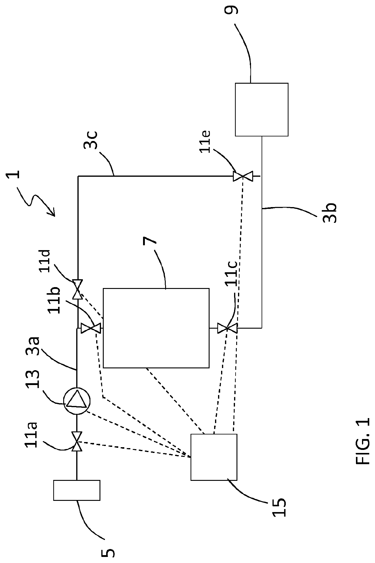
[0039]According to the invention a flow system is provided which flow system comprises at least one tube and at least one valve provided to said tube for controlling the flow through said tube. The at least one valve is provided downstream from a flow providing device provided in said flow system or in a connected flow system. The flow providing device could be for example at least one pump or a pressure vessel. The flow system comprises further a control system configured for controlling said at least one valve to be in three different states. A first state of the valve is an open state where the tube is kept open for allowing flow through the tube and a second and a third state of the valve are closed states preventing flow through the tube but with different closing force provided from the valve. A higher closing force is provided in the third state than in the second state.

[0040]Said method is a method for ensuring reliable opening of at least one valve. Furthermore, the steps o...


PUM


Abstract

A method for controlling at least one valve provided to a tube in a bioprocess flow system, said method comprising the steps of: —controlling the at least one valve to be in a first state, which is an open state when a flow through the tube should be allowed; —controlling the at least one valve to be in a second state during some parts of a process run in the system, said second state is a closed state were a first closing force is provided; and—controlling the at least one valve to be in a third state during some parts of a process run in the system, said third state is a closed state were a second closing force is provided which is a higher force than the first closing force.

Description

TECHNICAL FIELD OF THE INVENTION[0001]The present invention relates to a bioprocess flow system and to a valve and to a method for controlling at least one valve in a bioprocess flow system.RELATED ART[0002]In flow systems, for example systems for fluid transfer or fluid processing in the bioprocess industry, flexible tubes are often used for the transport of a fluid in the system. The bioprocess industry comprises processing of biopharmaceuticals, vaccines, gene therapy vectors, cells and other biomacromolecules / biological particles, including unit operations such as cell culture, filtration and / or chromatography. Flexible tube systems, together with other plastic components such as bags and fluid treatment devices, do provide cost-efficient solutions, i.e. when the flow systems are deployed pre-sterilized and used for single use applications, where the flow system is disposed after use.[0003]For controlling the flow of fluid in said flexible tubes, valves are used. A common valve ...

Claims


Application Information

Patent Timeline
Patent Type & Authority Applications(United States)
IPC IPC(8): F16K7/04F16K7/12F16K31/12F16K31/122F16K31/126
CPCF16K7/04F16K7/12F16K31/126F16K31/122F16K31/12
Inventor GEBAUER, KLAUS
Owner CYTIVA SWEDEN AB
Why Eureka
Try Eureka