Eureka AIR delivers breakthrough ideas for toughest innovation challenges, trusted by R&D personnel around the world.

Thermoacoustic temperature control system

Active Publication Date: 2021-03-04
CENTRAL MOTOR WHEEL CO LTD
View PDF0 Cites 0 Cited by
  • Summary
  • Abstract
  • Description
  • Claims
  • Application Information

AI Technical Summary

Benefits of technology

The patent text describes a way to prevent the transmission of acoustic energy in a thermoacoustic refrigeration system. This is done by inserting a blocking film near the heat exchanger on the low temperature side of the system. The blocking film allows the transmission of vibrational energy while preventing the acoustic mass flow from passing through. This improves the durability of the blocking film and ensures efficient energy transmission.

Problems solved by technology

The passage of the acoustic mass flow through the inside of the load makes it impossible to form an ideal temperature gradient between opposite end portions of a load-side heat accumulator because of the movement of the working gas.
Therefore, there is a problem in durability of the blocking film.

Method used


Image

  • Thermoacoustic temperature control system
  • Thermoacoustic temperature control system
  • Thermoacoustic temperature control system

Examples


Embodiment Construction

[0032]A thermoacoustic temperature control system 1 according to an embodiment of the present invention will be described below with reference to the drawings.

Configuration

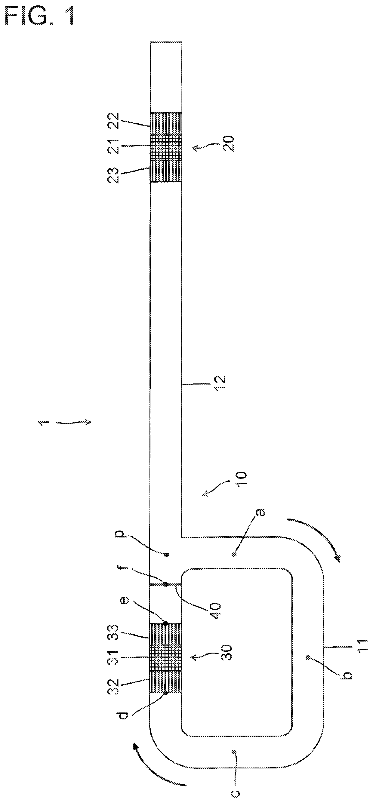
[0033]As illustrated in FIG. 1, the thermoacoustic temperature control system 1 includes a piping 10 made of a metal, a prime mover 20 incorporated in the piping 10, a load 30 incorporated in the piping 10 and a blocking film 40. As described later, the load 30 can function as a refrigerator that maintains a temperature of an object at a temperature that is lower than room temperature (refrigeration temperature) or a heater that maintains a temperature of an object at a temperature that is higher than room temperature. In other words, the thermoacoustic temperature control system 1 has a function that adjusts a temperature of an object connected to the load 30.

[0034]The piping 10 includes a looped piping portion 11, which is a piping part having a looped shape, and a branch piping portion 12 that branches from the...


PUM


Abstract

A system includes: a piping with a working gas encapsulated therein and a prime mover and load incorporated in the piping. The prime mover includes a prime mover-side heat accumulator and heat exchangers connected to opposite end portions of the heat accumulator. The load includes a load-side heat accumulator and heat exchangers connected to opposite end portions of the heat accumulator. The piping includes a looped piping portion having a looped shape and a branch piping portion branching from a branching point p in the looped piping portion, and the prime mover is incorporated in the branch piping portion and load is incorporated in the looped piping portion. A blocking film is inserted at a position in a vicinity of the branching point p. Consequently, a thermoacoustic temperature control system that enables enhancement in durability of a blocking film inserted in a part of a looped piping portion is provided.

Description

TECHNICAL FIELD[0001]The present invention relates to a thermoacoustic temperature control system.BACKGROUND ART[0002]Conventionally, thermoacoustic temperature control systems in which a prime mover and a load are incorporated in a piping with a working gas encapsulated therein have been known (see, for example, Patent Literature 1). The prime mover includes a prime mover-side heat accumulator and prime mover-side heat exchangers connected to opposite end portions, in an extension direction of the piping, of the prime mover-side heat accumulator. The load includes a load-side heat accumulator and load-side heat exchangers connected to opposite end portions, in the extension direction of the piping, of the load-side heat accumulator.[0003]This thermoacoustic temperature control system can be used as a thermoacoustic refrigeration system in which a refrigerator is employed as a load or a thermoacoustic heating system in which a heater is employed as a load. For example, the aforement...

Claims


Application Information

Patent Timeline
IPC IPC(8): F25B9/00
CPCF25B9/002F25B2700/21F25B9/145F25B2309/1403F25B2309/1405F25B2309/1409
Inventor FUKAYA, NORIYUKIITO, TAKESHIKASE, RYUUJYU
Owner CENTRAL MOTOR WHEEL CO LTD
Why Eureka
Eureka Blog
Learn More