

Defect display device and method
a display device and display device technology, applied in the field of defect display devices and methods, can solve the problems of high density of internal defects, difficult to see internal and difficulty in image interpretation, etc., and achieve the effect of not reducing the visibility of defects and their surrounding portions
- Summary
- Abstract
- Description
- Claims
- Application Information
AI Technical Summary
Benefits of technology
Problems solved by technology
Method used
Image

Examples
Embodiment Construction
[0035]The following describes an embodiment of a defect display device and method according to the present invention with reference to the accompanying drawings.
Defect Inspection Device
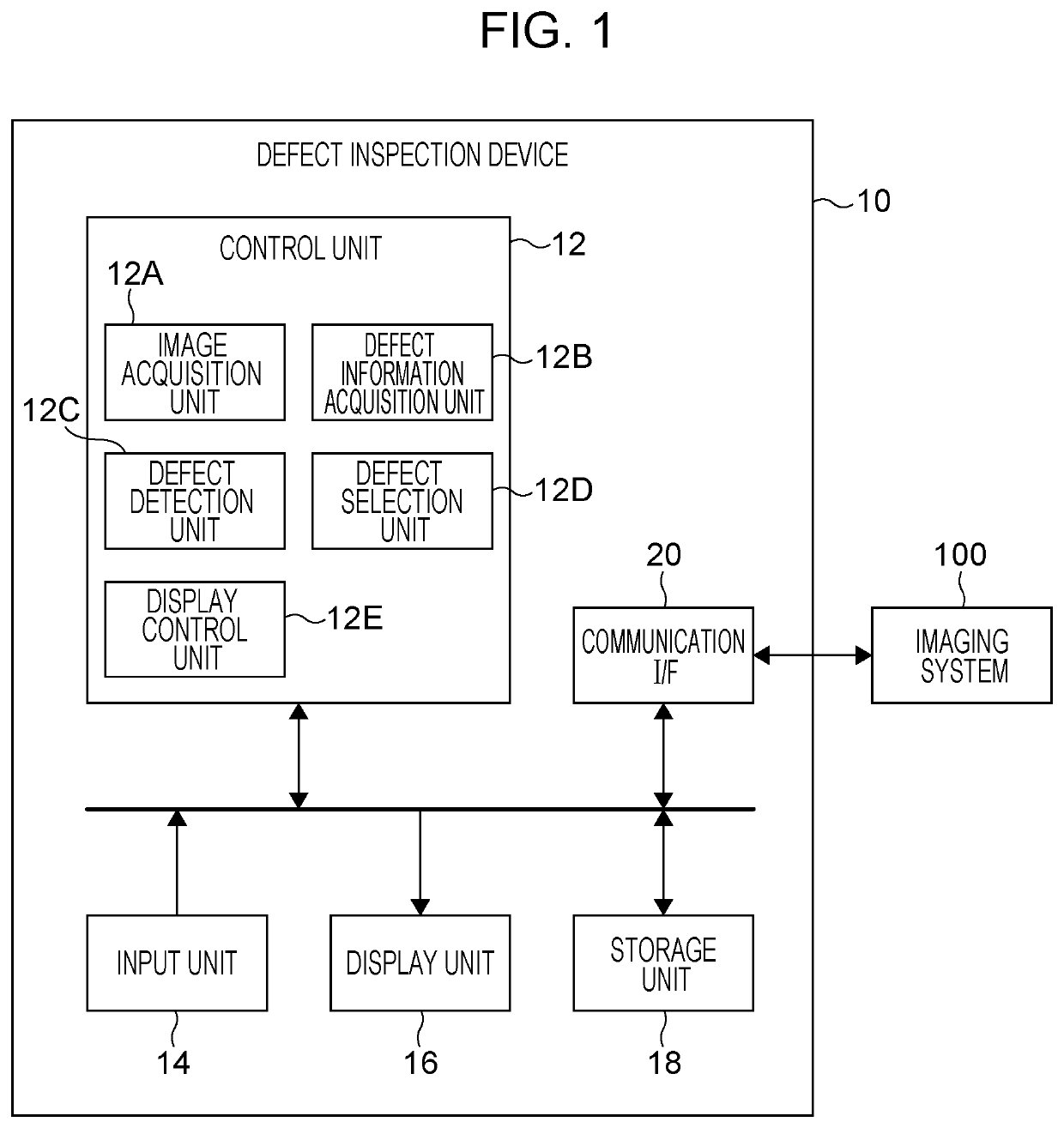
[0036]FIG. 1 is a block diagram illustrating a defect inspection device according to an embodiment of the present invention.
[0037]A defect inspection device 10 according to this embodiment is a device with which a user (image interpreter) performs nondestructive inspection of an industrial product such as a casting by using a radiographic image of the industrial product. The inspection-target industrial product is hereinafter referred to as an object OBJ.
[0038]As illustrated in FIG. 1, the defect inspection device 10 according to this embodiment includes a control unit 12, an input unit 14, a display unit 16, a storage unit 18, and a communication interface (communication I / F) 20. The defect inspection device 10 may be, for example, a personal computer or a workstation.
[0039]The control unit 12 includ...
PUM
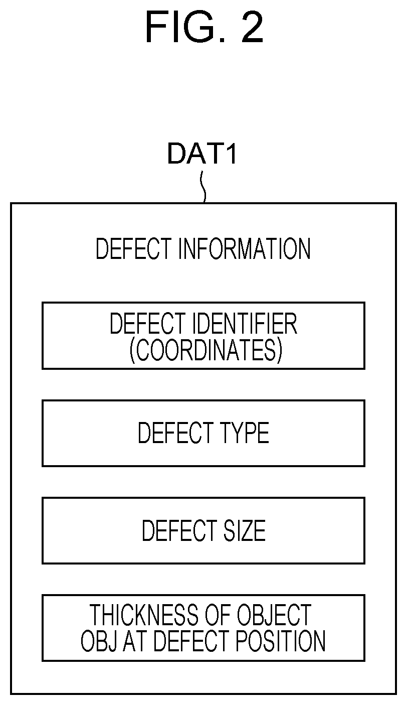
| Property | Measurement | Unit |
|---|---|---|
| thickness | aaaaa | aaaaa |
| size | aaaaa | aaaaa |
| thickness | aaaaa | aaaaa |
Abstract
Description
Claims
Application Information