
Display device, sensor panel, position-detecting device, position-inputting device, and computer system

a technology of display device and display screen, which is applied in the direction of liquid/solution decomposition chemical coating, superimposed coating process, instruments, etc., can solve the problems of affecting generating bringing about a lot of noise for the display device, so as to achieve the effect of reducing the visibility of the display screen and ensuring the effect of production efficiency

Active Publication Date: 2012-01-03
WACOM CO LTD
View PDF3 Cites 16 Cited by
  • Summary
  • Abstract
  • Description
  • Claims
  • Application Information

AI Technical Summary

Benefits of technology

The present invention provides a display device with overlapping wiring that does not reduce the visibility of the display screen. This is achieved by providing a detection conductor with a narrow line portion that is difficult to see and a base line portion formed of a conductor of a predetermined width. The detection conductor includes a plurality of narrow line conductors connected in parallel, which minimizes the impact on the visibility of the screen. The sensor panel can be used with a display device and includes a plurality of detecting conductors extending along a major plane of the sensor panel. The invention also provides a display panel with a substrate, at least one conductive layer, and a pixel layer having a plurality of pixel units that transmit light based on operation of the segment electrodes. The sensor panel can be used in a display mode and a sensing mode.

Problems solved by technology

Typically, a display device such as a liquid crystal display device generates a lot of noise.
Also, if other devices such as a substrate and the like are provided below a display device in an overlapped manner, a lot of noise is brought about by those devices (i.e., by the substrate and the like).
However, since wiring of the loop coil is located on a display screen, the wiring may be visible when the display screen is being watched such that visibility of the display screen is adversely affected by the loop coil.

Method used


Image

  • Display device, sensor panel, position-detecting device, position-inputting device, and computer system
  • Display device, sensor panel, position-detecting device, position-inputting device, and computer system
  • Display device, sensor panel, position-detecting device, position-inputting device, and computer system

Examples


example 1

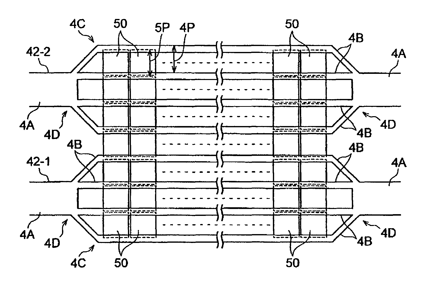
[0136]FIG. 9 is an enlarged plan view illustrating a structure of loop coils according to an exemplary embodiment of the present invention.

[0137]In FIG. 9, loop coils 42-1 and 42-2 are illustrated as an example. The structure of all the loop coils in loop coil groups 42 and 44 may be similar to the structure of the loop coils 42-1 and 42-2 illustrated in FIG. 5.

[0138]In the structure illustrated in FIG. 9, instead of the branch-connecting portion 4D of the loop coils 42-1 and 42-2 in the above-mentioned embodiment, a branch-connecting portion 4E is provided. The branch-connecting portion 4E is a portion where the base line portion 4A meets the narrow lines 4B (i.e., a connection portion). The branch-connecting portion 4E is made of a conductor similar to the base line portion 4A and the narrow lines 4B. The branch-connecting portion 4E has a shape which expands between narrow line portions 4C at both ends of the narrow lines 4B, outside of a display region of the display panel 5 (se...

example 2

[0139]FIG. 10 is a cut out perspective view illustrating a structure of a display panel according to another exemplary embodiment of the present invention.

[0140]In this example, loop coils of loop coil groups 42 and 44 are formed inside a liquid crystal display panel 6.

[0141]The liquid crystal display panel 6 illustrated in FIG. 10 includes a polarization plate 61, a glass substrate 62 disposed on the polarization plate 61, a transparent conductor layer 63 disposed on the glass substrate 62, a liquid crystal layer 64 disposed on the transparent conductor layer 63, a transparent conductor layer 65 disposed on the liquid crystal layer 64, a color filter 66 disposed on the transparent conductor layer 65, a glass substrate 67 disposed on the color filter 66, and a polarization plate 68 disposed on the glass substrate 67. The liquid crystal display panel 6 emits light from below, for example, by using a cold-cathode tube backlight.

[0142]The liquid crystal display panel 6 is divided into ...


PUM

PropertyMeasurementUnit
widthaaaaaaaaaa
widthaaaaaaaaaa
resonance frequencyaaaaaaaaaa

Abstract

A display device is provided. The display device includes a display screen having a light-transmissible display conductor extending in a predetermined plane, and at least one detection conductor extending along the predetermined plane, the at least one detection conductor having at least one base line portion formed of a conductor of a first width and a narrow line portion including a plurality of narrow-line conductors of a second width connected in parallel between the at least one base line portion.

Description

CROSS REFERENCES TO RELATED APPLICATIONS[0001]The present application claims priority from Japanese Application No. P2006-078959 filed on Mar. 22, 2006, which application is incorporated herein by reference and to which priority is claimed.FIELD OF THE INVENTION[0002]The present invention relates to a display device, a sensor panel provided in the display device, a position-detecting device including the sensor panel, a position-inputting device having the position-detecting device and a position indicator, and a computer system including the position-inputting device.BACKGROUND OF THE INVENTION[0003]Generally, position-detecting devices which detect positions indicated by pen-type position indicators are known. For example, Japanese Published Patent Application No. 2002-215317 discloses a product in which a position-detecting device integrally formed with a liquid crystal display device is used and a position-inputting operation can be carried out by operating a position indicator ...

Claims


Application Information

Patent Timeline
Patent Type & Authority Patents(United States)
IPC IPC(8): G06F3/045G09G5/00G06F3/044G08C21/00
CPCG06F3/03545G06F3/0412G06F3/046G06F2203/04103G06F3/04184
Inventor ITO, MASAMITSU
Owner WACOM CO LTD
Learn More